- Mark as New
- Bookmark
- Subscribe
- Mute
- Subscribe to RSS Feed
- Permalink
- Report Inappropriate Content
Hello,
I'm having trouble creating my own component that uses Avalon Streaming Interface in QSys. Based on the VIP demonstartion for DE1-SoC I want to have a connection between the Altera VIP Frame Reader and Alpha Blending Mixer (to process the frames that are sent). In order to do that I created a VHDL file and created a new component in QSys, specyfing the data, valid, ready, startofpacket and endofpacket signals since these are the ones used by Frame Reader and Blending Mixer. I check if the valid and ready signals are asserted and then just pass the data, startofpacket and endofpacket signals through. In QSys I also needed to add Timing Adapters before and after my component because of Ready Latency. Unfortunately, the frames flows continously and are moving through the vga screen so I believe there's something wrong with the logic in my component. I check the signals at the rising edge of the clock. I'm new to the Avalon stuff and I'm sure I'm missing something really simple in the code. I attach it below. Could you help me find what's missing in here?
LIBRARY ieee;
USE ieee.std_logic_1164.all;
ENTITY simple_avalon_interface IS
PORT (
clock, resetn : IN STD_LOGIC;
din_startofpacket : in std_logic;
din_endofpacket : in std_logic;
din_valid : in std_LOGIC;
din_ready : out STD_LOGIC;
din_data : in STD_LOGIC_VECTOR(23 DOWNTO 0);
dout_startofpacket : out std_logic;
dout_endofpacket : out std_logic;
dout_valid : out std_LOGIC;
dout_ready : in STD_LOGIC;
dout_data : out STD_LOGIC_VECTOR(23 DOWNTO 0)
);
END simple_avalon_interface;
ARCHITECTURE Structure OF simple_avalon_interface IS
BEGIN
process (clock,dout_ready,din_valid)
begin
if (rising_edge(clock)) then
    if (dout_ready ='1' and din_valid = '1') then
        dout_valid <= '1';
        din_ready <= '1';
        dout_data <= din_data;
        dout_startofpacket <= din_startofpacket;
        dout_endofpacket <= din_endofpacket;
    else
        dout_valid <= '0';
        din_ready <= '0';
    end if;
end if;
end process;
END Structure;
Link Copied
- Mark as New
- Bookmark
- Subscribe
- Mute
- Subscribe to RSS Feed
- Permalink
- Report Inappropriate Content
Weird timing I was creating a training and drew a picture of what a streaming dual clock FIFO would look like. Here is the diagram which will give you an idea how to capture or send data to/from a streaming port.
What were you intending with your core, to add a pipeline stage between two streaming cores? If so I think there is a streaming pipeline stage in Qsys already.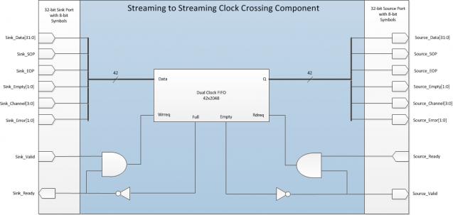
- Mark as New
- Bookmark
- Subscribe
- Mute
- Subscribe to RSS Feed
- Permalink
- Report Inappropriate Content
BadOmen, thank you for the diagram. What I want to do is to have a core between two streaming cores just as the Streaming Pipeline Stage you mentioned but I need to receive the streamed data, change it and drive it to the source so I cannot use the ready QSys component. But I inserted the Streaming Pipeline Stage to my project instead of my component and it's working so what I actually need is the Pipeline Stage logic for receiving and sending data.
- Mark as New
- Bookmark
- Subscribe
- Mute
- Subscribe to RSS Feed
- Permalink
- Report Inappropriate Content
If your transform is combinatorial what you could do is create a component that has a source and a sink with the sink data transformed and sent to the source. Then you would wire the ready and valid bits directly so that all your component does is transform the data. Then if that's too much combinational delay and you need it pipelined put that Qsys pipeline stage after your core.
Often when I'm building stuff like this I have FIFOs too which helps isolate the source and sink. Last but not least another thing you can do is pipeline the transformed data and the valid from the sink and use the ready from source to enable the registering of those two signals and specify in the component defining that it has a ready latency of 1. Something like this in Verilog:
always @ (posedge clk)
begin
  if ((snk_valid == 1) & (src_ready == 1)
  begin
    src_data <= transformed_snk_data;   // need to make sure data is held in cause the src_ready deasserts on the next clock cycle
  end
  src_valid <= snk_valid;
end
That code above is only safe if the ready latency of the source port is declared as 1. What Qsys will do is resynchronize the data output from your core. So basically when your component is being fed valid data and the source is being told that the downstream is ready for data you capture your data. On the next clock cycle if the downstream IP is still ready for the data then it gets sent, and if it's not ready then the data is held. Since the ready latency of the source is 1 Qsys will put a timing adapter into the path that compensates for the fact that valid data takes an extra clock cycle to get through your core. You could build the same sort of compensation into your IP but then you are re-inventing the wheel. Hopefully you can now see why I put FIFOs in a lot of the streaming IP I build, it helps isolate the flow of data by decoupling the source from the sink.
- Mark as New
- Bookmark
- Subscribe
- Mute
- Subscribe to RSS Feed
- Permalink
- Report Inappropriate Content
Thank you for detailed explanation. Right now I created a component with valid, ready, startofpacket, endofpacket bits directly wired and I did the same with the data. So basically all my component does is sending the data through. I attached it to the end of the ST Frame Reader, and put the QSys pipeline after as you suggested. But unfortunately it's not working.
Is it because of the delay in the signals? For example if I changed the readyLatency would it compensate for the fact that the data is streamed through one more component along the way? I know that streaming interface is easy, but I kind of got lost in the way I guess.- Mark as New
- Bookmark
- Subscribe
- Mute
- Subscribe to RSS Feed
- Permalink
- Report Inappropriate Content
Ready latency only compensates for the pipelining within your own component and doesn't take the rest of the system into consideration. So if you pipelined the data, valid, sop, eop signals you would declare that to have a ready latency of 1 because valid data gets asserted one cycle after the source ready signal asserts. Section 5.9 shows some examples of what I mean by ready latency: https://www.altera.com/content/dam/altera-www/global/en_us/pdfs/literature/manual/mnl_avalon_spec.pdf
If you don't put any pipeline stages into your core then by definition it must set the ready latency to 0. If the delay through your core is too high then you should see a setup timing violation from the path through your IP core. Have you simulated your design, typically for functional timing issues simulations will make finding these issues much easier. Alternatively you could signaltap the source and sink ports of your core to see how it behaves in silicon, but you need to make sure those paths meet timing otherwise you will not be able to trust the samples collected.- Mark as New
- Bookmark
- Subscribe
- Mute
- Subscribe to RSS Feed
- Permalink
- Report Inappropriate Content
Thank you for explaining that to me. Since I'm not using any pipelining just for now I assume that my ready latency is 0. I tried to signaltap my design but since I'm not meeting the timings just as you set I just get zeros and none of the sources and sinks have any valuable data (is it normal for signaltap to set all of the other sources and signals even before my component to 0? Because I also tried to look at the signals in the frame reader but they are also just 0).
Anyway, is there a simple way to simulate and testbench the whole QSys system? Because I would like to see how the whole flow of data behaves. I found sth like this, would it do the trick? http://www.alterawiki.com/wiki/simulating_designs_with_lower-level_qsys_systems- Mark as New
- Bookmark
- Subscribe
- Mute
- Subscribe to RSS Feed
- Permalink
- Report Inappropriate Content
I suspect the capture register of the Signaltap module isn't meeting timing either and as a result you don't capture the data correctly. Think of signaltap as a big FIFO that wires up to your logic so if that doesn't meeting timing then the samples will not be stable. Another thing to take a look at are the Quartus warnings from the compilation, it could be an RTL mistake causing the behavior you are seeing as well such as an unconnected wire or synthesis optimizations. You can have Quartus filter on message types which makes it easier to find those, just look for ones that match up with your IP core name.
Yes you can simulate the entire Qsys system. You can have Qsys output simulation models for everything in your system or generate a testbench for you. When it generates a testbench for you it attempts to hook up bus functional models (BFM) to the ports exposed out of your system such as clocks, resets, Avalon, AMBA, etc... Clocks and resets will have their BFMs automatically driven but if you expose Avalon-ST ports for example you'll have to write code to drive those BFMs.- Mark as New
- Bookmark
- Subscribe
- Mute
- Subscribe to RSS Feed
- Permalink
- Report Inappropriate Content
Thank you for your answer. Actually I didn't have to perform any simulation as my mistake was in the ready latency, but I fixed it and now I'm able to send data through my component.
Now I have another problem because I need to modify the data that comes through my IP but I'm not quite sure how to interpret the fact that the data is sent with the control packet. My first thought was that if I have a 24 bit wide data stream the 3 x 8 bits correspond to the R,G,B values respectively and that's it. But when I tried to change the data the component stops working. The Avalon specification doesn't state if I should take something into consideration when accessing the data. Do you have any experience in that?- Mark as New
- Bookmark
- Subscribe
- Mute
- Subscribe to RSS Feed
- Permalink
- Report Inappropriate Content
Typically with video I split the components out to their own individual symbols. So for 24-bit colour that would be 8-bit symbols for R, G, and B. If you use that format then everything hooked up to your core needs to use the same format of 8-bit symbols. If control needs to be in-band (moves with the data) then you could have an additional symbol that carries that information assuming it fits into an 8-bit wide value.
It's not uncommon to have small gaskets in the video stream that handle formatting. For example a while back we built a frame buffering subsystem that read the frame 64-bit at a time from memory and output it as 64-bit ST data, we then took that data and turned it into 32-bit data, then we took that 32-bit data and ripped the alpha channel off and provided 24-bit colour to the synchronizer that output the video to the screen. Everything but the alpha channel removal was available in Qsys so we build a little gasket that had 32-bit data on one side and 24-bit on the other. The Avalon-ST spec is fairly generic and assumes that if you have any encoding in your data you handle it internal to your IP(s). Qsys just knows about the ports and the number of symbols per beat your IP exposes so that if you hook up two IP together it can attempt to adapt one over to the other. Now if you had say 8-bit symbols for one IP and connect it to another component that uses 24-bit symbols there is no way Qsys can adapt that since the fundamental data units are different but those sorts of things are easy to overcome with gasket IP blocks.- Mark as New
- Bookmark
- Subscribe
- Mute
- Subscribe to RSS Feed
- Permalink
- Report Inappropriate Content
Ok, so if I have 24-bit data at the input should I decode it first to know that I'm dealing with pixels rather than control data? And then split the components to have the symbols for R,G and B respectively?
- Mark as New
- Bookmark
- Subscribe
- Mute
- Subscribe to RSS Feed
- Permalink
- Report Inappropriate Content
Yes, you'll not want to change the control packets. The first 4 bits of a packet (these are the lowest 4 bits in your data width, so if you're using 24 bits the first 24-bit word will have the code in bits 3-0 and 23-4 are not used) will have a code that shows whether it's a control packet or not. If the first 4 bits are 0 then it's a video packet, if it's 15 then it's a control packet. 1-8 are reserved for custom user packets, 9-12 for Altera future use, 13 = Ancillary data, 14 reserved for Altera future use.
0 and 15 are definitely correct. The text suggests 7 user packets and 5 future Altera packets, so there is some ambiguity about the others. My guess is 8 is wrong as a user packet. I should add that it's all on page 2-10 of the ug_vip.pdf guide.- Mark as New
- Bookmark
- Subscribe
- Mute
- Subscribe to RSS Feed
- Permalink
- Report Inappropriate Content
G'day BadOmen,
Thank you for taking the time to respond in detail. Your advice is really useful for newbies like me! Your clue later in this thread is vital: The Avalon-ST Video Protocol, detailed in Section 2 of the VIP Users Guide, is essential reading for implementers. It looks like the simple solution below may be *too* simple. We need to avoid processing control packets as if they contain pixel data, and the first value of every packet never contains pixel data. So the core can't just process sink data on every src_valid cycle. I'm working on a couple of cores with relatively deep pixel pipelines which, similar to this example, are insensitive to the content of the control packets. Is there a "right" way, in general, for managing control packets for such a core? Hopeful thanks ... --- Quote Start --- If your transform is combinatorial what you could do is create a component that has a source and a sink with the sink data transformed and sent to the source. Then you would wire the ready and valid bits directly so that all your component does is transform the data. Then if that's too much combinational delay and you need it pipelined put that Qsys pipeline stage after your core. Often when I'm building stuff like this I have FIFOs too which helps isolate the source and sink. Last but not least another thing you can do is pipeline the transformed data and the valid from the sink and use the ready from source to enable the registering of those two signals and specify in the component defining that it has a ready latency of 1. Something like this in Verilog:
always @ (posedge clk)
begin
  if ((snk_valid == 1) & (src_ready == 1)
  begin
    src_data <= transformed_snk_data;   // need to make sure data is held in cause the src_ready deasserts on the next clock cycle
  end
  src_valid <= snk_valid;
end
That code above is only safe if the ready latency of the source port is declared as 1. What Qsys will do is resynchronize the data output from your core. So basically when your component is being fed valid data and the source is being told that the downstream is ready for data you capture your data. On the next clock cycle if the downstream IP is still ready for the data then it gets sent, and if it's not ready then the data is held. Since the ready latency of the source is 1 Qsys will put a timing adapter into the path that compensates for the fact that valid data takes an extra clock cycle to get through your core. You could build the same sort of compensation into your IP but then you are re-inventing the wheel. Hopefully you can now see why I put FIFOs in a lot of the streaming IP I build, it helps isolate the flow of data by decoupling the source from the sink. --- Quote End ---
- Mark as New
- Bookmark
- Subscribe
- Mute
- Subscribe to RSS Feed
- Permalink
- Report Inappropriate Content
rockoff, if I understand correctly, you want to have a component that performs some computations on the pixel values so you want to avoid changing the control packets, right? If yes, then you can detect the start of packet input signal and then check the least for bits of data input. if they're "0000" then the next packet that will arrive is the pixel value. To give you an example:
 if DIN_SOP = '1' then
	if DIN_DATA(3 downto 0) ="0000" then
	      --set some signal to know that you're dealing with pixels next
                 data_pkt <= '1';
Hope this helps you a little
- Mark as New
- Bookmark
- Subscribe
- Mute
- Subscribe to RSS Feed
- Permalink
- Report Inappropriate Content
Hi Korn,
Thank you for this helpful reply. Yes, I'm inserting pixel-processing components into a video pipeline. The new components must respect the VIP streaming protocol so that they'll interoperate correctly with VIP suite cores. One way or another, we're required to implement a state machine to keep track of what just came in on din_data. Indeed, checking the low-order nibble when SOP is asserted, as you suggest, is essential. I'm wrestling with a simplest such state machine. Since every single IP core to be connected to a VIP suite core requires this logic, I'm surprised that there is no example in the VIP Suite User Guide or on the forum. Maybe I'm just missing it?- Subscribe to RSS Feed
- Mark Topic as New
- Mark Topic as Read
- Float this Topic for Current User
- Bookmark
- Subscribe
- Printer Friendly Page