FPGA Intellectual Property
PCI Express*, Networking and Connectivity, Memory Interfaces, DSP IP, and Video IP
6343 Discussions

Stratix 10 Mailbox Client IP Interface

WGith
Beginner
2,161 Views

Hi,


I am trying to interface with the SDM via the Mailbox Client IP. I have created my own AVALON like interface to communicate with the mailbox client. I have been able to successfully read the Command FIFO Empty Space @ Addr Base + 2, and the ISR @ base +8. I have also been able to write and read back sucessfully changes to the IER@ base +7.


Where I am having problems is with actually interfacing with the SDM via the actual Codes, for example GET_IDCODE. I watched the youtube video about the Mailbox Client and I am trying to reproduce the GET_IDCODE example. Here is what I am doing.


Interface Clock is 100 Mhz.


  1. I write 0x10, which is the GET_IDCODE into the writedata signal.
  2. I set the address signal to 0x1 as it is a zero command length command.
  3. I send a single clock width pulse to the write signal.
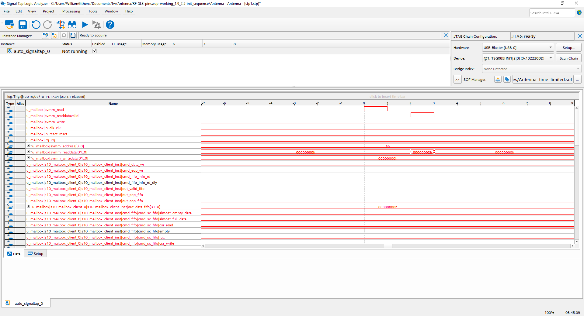
  4. I then read back the ISR register and I always see 0x2h, not 0x3h as expected.


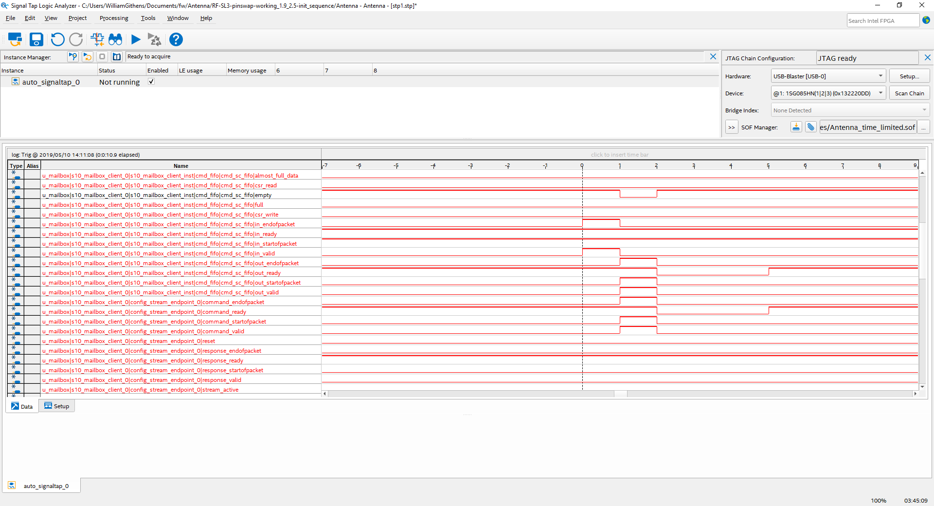
I do some additional checking by reading the Command FIFO empty space register and I do see that the command fifo level doesn't change. In signaltap I see that the command goes into the fifo and is then popped out, but there is no response after that.


I have made sure that this is the only IP interfacing with the SDM. I made sure to reset the block for at least 2 clock cycles as the user guide stipulates.


Any additional guidance would be appreciated.


I am signaltapping signals deep in the autogenerated mailbox client and I see the command request go to internals that I can't see, but never a valid response back.

0 Kudos
15 Replies
WGith
Beginner
1,652 Views

I forgot to mention I generated the IP using 19.1 Pro.

0 Kudos
YuanLi_S_Intel
Employee
1,652 Views
Hi William, Just would like to check, after the execution of 0x10 (GET_IDCODE command), have you check the ISR value? The ISR value has to be 0x1 to show that the execution of command is successful. Then, read base + 5 for 2 times. The first time, probably you will get the header value, then for the 2nd time, you will get the IDCODE. Hope it helps. https://www.intel.com/content/dam/www/programmable/us/en/pdfs/literature/ug/ug-20087.pdf (Page 15) Regards, YL
0 Kudos
WGith
Beginner
1,652 Views
Hi Yes right after I write the ID command I read the ISR and it is always 0x2 in hex. The signaltap captures I have show the command enter and then exit the fifo as expect and then I assume goes to the SDM which I cannot capture in Signaltap. I have never see any response, even an error response packet return. Is there any special setting I need to enable in my design? Is there any time limit on reading a response once I send a command? I will attach a couple signaltap captures later today to show me sending the IDCODE and CHIP ID commands. Thank you Will Get Outlook for Android<https://aka.ms/ghei36>
0 Kudos
WGith
Beginner
1,652 Views

Here is a couple of signal tap captures. The Write IDCODE is the writing of 0x10. As you can see it enters the fifo and then continues on. I don't see a response though.

0 Kudos
WGith
Beginner
1,652 Views

This is the second half of the previous signaltap. This shows the command being read out of the fifo and heading to the SDM.

0 Kudos
WGith
Beginner
1,652 Views

Here is the signaltap showing that reading the ISR is always 0x2h

0 Kudos
YuanLi_S_Intel
Employee
1,652 Views
Hi William, I have tested the command on v19.1 Pro and it seems like there is no problem in executing it. It seems to me that it might be due to command execution flow issue. I have included the flow to execute the command in TCL using system console: global omp b0 b1 b2 b3 b4 b5 b6 b7 b8 #writing the command header (Get_IDCODE) master_write_32 $omp $b1 0x00000010 #Read ISR (Expect to get 0x3) set ISR [master_read_32 $omp $b8 1] while {$ISR != 0x00000003} { puts "ISR is not ready yet!" set ISR [master_read_32 $omp $b8 1] } #Read Response FIFO fill level, EOP and SOP (Expect to get 0x9) (optional) set SOP_EOP_FIFO [master_read_32 $omp $b6 1] while {$SOP_EOP_FIFO != 0x00000009} { puts "SOP_EOP_FIFO is not ready yet!" set SOP_EOP_FIFO [master_read_32 $omp $b6 1] } #read offset 5 for the first packet of data (Expect to get 0x1000) master_read_32 $omp $b5 1 #Read Response FIFO fill level, EOP and SOP (Expect to get 0x6) (optional) set SOP_EOP_FIFO [master_read_32 $omp $b6 1] while {$SOP_EOP_FIFO != 0x00000006} { puts "SOP_EOP_FIFO is not ready yet!" set SOP_EOP_FIFO [master_read_32 $omp $b6 1] } #read offset 5 again to retrieve the response argument (in this case, this command only has one response argument, which is the IDCODE) master_read_32 $omp $b5 1 Hope it helps. Thanks, YL
0 Kudos
WGith
Beginner
1,652 Views
Hi, I was able to figure out my problem. I was given AN 891, Using the Reset Release Intel Stratix 10 FPGA IP. I didn’t change anything in my code except connected up this block to my reset signals and now I see 0x3h as my response in the ISR. Thank you, --Will
0 Kudos
WGith
Beginner
1,652 Views
Hi, I have run into a related issue with the mailbox client. I am able to perform the following commands successfully. 0x0 NOP 0x10 GET_IDCODE 0x12 GET_CHIPID 0x13 GET_USERCODE. 0x4 CONFIG_STATUS I have however unable to perform either of the following 2 commands. 0x5c RSU_IMAGE_UPDATE 0x5b RSU_STATUS In both cases, I get the response of 0x1 in the response header which means either INVALID_COMMAND or in the case of RSU_IMAGE_UPDATE, it “Returns non-zero response if the device is already processing a configuration.” I don’t know what that means exactly. Is the SDM still talking to the active serial x4 device and I can communicate with it? I am running my image on the fpga with no issue, so I would think that I should be able to communicate with the device to send a reconfig command. What I am trying to do is to have the fpga load the default image, and then I want to reconfigure the fpga to load a different image at an offset. FYI: When I ran the CONF_STATUS command, I received the following results: Word 0: 0x0 Word1: 0x0 Word 2:0xC000000b (nStatus & nConfig are ‘1’, MSEL is “001”, The other bit ‘1’ @ location 3 is reserved, so I don’t know what that means.) Word 3: 0xc Word 4 0x0 Word 5: 0x0 Any help / guidance would be appreciated. --Will
0 Kudos
WGith
Beginner
1,652 Views
Hi, I found one mistake in my code (regarding length), so I fixed that. Hopefully I get it figured out soon. --Will
0 Kudos
WGith
Beginner
1,652 Views
Hi, I fixed my length issue, but still no luck with either command 0x5c, or 0x5b. It always returns 0x1 (invalid command)
0 Kudos
YuanLi_S_Intel
Employee
1,652 Views
Hi William, This is expected if your S10 Design doesnt contain a remote system update host controller and a Mailbox Client Intel Stratix 10 FPGA IP. Please refer to link below for the design needed to perform RSU. https://www.intel.com/content/dam/www/programmable/us/en/pdfs/literature/hb/stratix-10/ug-s10-config.pdf (Page 122) Regards, YL
0 Kudos
WGith
Beginner
1,652 Views
HI, I followed the app note and created the following mapping. BLOCK START ADDRESS END ADDRESS BOOT_INFO 0x00000000 0x0010FFFF FACTORY_IMAGE 0x00110000 0x00487FFF (0x00443FFF) SPT0 0x00488000 0x0048FFFF SPT1 0x00490000 0x00497FFF CPB0 0x00498000 0x0049FFFF CPB1 0x004A0000 0x004A7FFF P1 0x004A8000 0x007DBFFF Configuration device: 1SG085HN1AS Configuration mode: Active Serial x4 Notes: - Data checksum for this conversion is 0xB3D7AA8A - All the addresses in this file are byte addresses I then loaded the flash with my new .jic file and then loaded the design. I am now able to get status back from usercode 0x5b which points that I loaded the image at 0x004A8000. I still can’t get user command 0x5C to work no matter what I do. I am sending the following commands at the moment Base+0 , 0x5C(command), 0x2 (length) Base+0, 0x0(command), 0x0(length) Base+1, 0x004A8000(start address)
0 Kudos
WGith
Beginner
1,652 Views

I took a look at the TCL file and I realized I was doing the 2 words of data in the incorrect order. It needs to be the 0x004A8000 data first and then 0x0. I tried that and I still get 0x1 as my response. It seems that I get the error command as soon as I send the first command. The data I am sending to base+0 is 0x0000205C. I don't know what else to do to get a valid response.


I am continuing to read the tcl file and see if there is anything I could have missed.

0 Kudos
WGith
Beginner
1,652 Views

Hi,


I figured out the issue. I was not writing the multiple length commands correctly. I was able to reinit the FPGA.


Thank you for you help. Consider this case closed.

0 Kudos
Reply