- Mark as New
- Bookmark
- Subscribe
- Mute
- Subscribe to RSS Feed
- Permalink
- Report Inappropriate Content
Hello,
I am writing this post just to share a sample project (see the attached zip) for the DE2-115 board which grabs video frames from the onboard the ADV7180 TV Decoder and outputs them to 640x480 VGA through the ADV7123 DAC using only SoPC and the VIP suite. The DE2_115_TV example contained in the Terasic DVD, which is the only example working with PAL sources I was able to find on the internet, does not take advantage of the VIP suite, rather relies on custom verilog modules, IMHO very difficult to integrate in other designs (especially when NIOS is involved) I wasted several days in order to make it work with the VIP suite (clocked video input -> chroma resample -> ... -> deinterlacer ->clocked video output) and it was quite hard for me to find enough documentation to configure properly the timing parameters of the clocking video I/O and the correct sequence for decoding ITU-R.656 to RGB. I am sharing this project (which works correctly with both PAL and NTSC sources) with the hope that it will help someone else in the future that encounters the same problem as mine. Note: this example uses the SDRAM memory for keeping the 640x480 RGB frame-buffer. I have another working variant which uses the smaller SRAM (2 Mb) for the FB, downsampling the captured frames to 320x240 and then upsampling to 640x480 before the video_output. Feel free to contact me if you need it. Regards, PrimianoLink Copied
24 Replies
- Mark as New
- Bookmark
- Subscribe
- Mute
- Subscribe to RSS Feed
- Permalink
- Report Inappropriate Content
Hi,
I am trying to do almost the same design but with DVI input and output. I have been able to achieve only a part of it. The part where I can get input from the CVI -> frame buffer -> DDR2 memory -> CVO works fine but when I try to introduce other vip suite components such as chroma sampler or even a simple clipper it gives me no results.Can you help me with the correct parameters for DVI if you have any?- Mark as New
- Bookmark
- Subscribe
- Mute
- Subscribe to RSS Feed
- Permalink
- Report Inappropriate Content
I haven't worked with DVI yet.
Anyway what is important to understand is the format used by the DVI video decoder. What kind is it? RGB? 4:2:0 YCbCr? Another important thing is the order of the video processing stages in the video pipeline. My best advice would be to put the framebuffer as the last stage, just before the CVO, and enable both frame dropping and replication. In this way it will fully compensate underflows and overflows of the video pipeline. If you provide more details about the video format I can try to give some hints. Regards, Primiano- Mark as New
- Bookmark
- Subscribe
- Mute
- Subscribe to RSS Feed
- Permalink
- Report Inappropriate Content
Hi,
Thanks for reply.I am using RGB DVI .The input is cuming from the PC through DVI in and the output through the FPGA board to the DVI panel on computer LCD.I am using frame buffer before the DVI output which is reading and writing from DDR2 memory.I already checked DDR2 memory independently.- Mark as New
- Bookmark
- Subscribe
- Mute
- Subscribe to RSS Feed
- Permalink
- Report Inappropriate Content
Are you sure the frame at the end has the correct size expected by CVO? Try a simple pipeline with CVI > scaler (reduce the frame size /2) -> scaler(restore to original size *2) -> framebuffer -> CVO
- Mark as New
- Bookmark
- Subscribe
- Mute
- Subscribe to RSS Feed
- Permalink
- Report Inappropriate Content
HI ,
Thanks for help I posting my current working design which is working ..But when I try to extend this pipeline by adding more components from vip suite it wont give an output.I dont know why.I cannot even simulate it in modelsim.It complains about license.So I am not able o find out where the problem exactly lies. And I will try your suggestion and see if it works.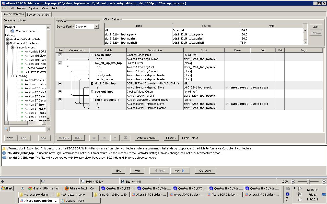
- Mark as New
- Bookmark
- Subscribe
- Mute
- Subscribe to RSS Feed
- Permalink
- Report Inappropriate Content
Just a couple of questions more:
What device are you using? Are you sure your design can be clocked @ 150MHz? Have you verified it with TimeQuest? Primiano- Mark as New
- Bookmark
- Subscribe
- Mute
- Subscribe to RSS Feed
- Permalink
- Report Inappropriate Content
Hi sneha22,
I understand your system is working fine as-is but I do not think the SOPC Builder fabric can preserve Avalon-MM bursts through the clock-crossing adapter. Memory accesses may be quite inefficient and you may have trouble while expanding the design in the future. The frame buffer already comes with dual-clock FIFOs and you just need to enable them in the GUI. Before you try adding more components, you should make sure that you can configure the CVO properly for the output resolution you are targetting. You may use the test pattern generator IP for that purpose. vgs- Mark as New
- Bookmark
- Subscribe
- Mute
- Subscribe to RSS Feed
- Permalink
- Report Inappropriate Content
Hi
I am sorry for the late reply i have been trying some designs out.. The board is cyclone3 EP3C120F7 development board.I am clocking the DDR memory and other components at 150 Mhz.. But when I verified with time quest I have failures in Setup and hold time, but still I was able to see the output on the hardware on the DVI output. I also think that the failures are due to improper timing constraints but I am not sure how to correct them?- Mark as New
- Bookmark
- Subscribe
- Mute
- Subscribe to RSS Feed
- Permalink
- Report Inappropriate Content
What happens if you downclock to 100Mhz? (VIP and VOP can still handle different clock rates)
- Mark as New
- Bookmark
- Subscribe
- Mute
- Subscribe to RSS Feed
- Permalink
- Report Inappropriate Content
Hi vgs,
I have been able to get the CVO output and I also checked the design by removing the clock crossing bridge and had the same output as before .I didnot make any difference.But I have been having problems with the timimgs.I get a negative slack. I dont know how to go about it?- Mark as New
- Bookmark
- Subscribe
- Mute
- Subscribe to RSS Feed
- Permalink
- Report Inappropriate Content
Hi,
I am not an expert with timing closure related issues but you probably need to be more explicit regarding this negative timing slack if you want someone else to be able to help. What is the path with an issue? What are the nodes involved? The deinterlacer and the frame buffer come with a SDC file to declare false timing paths. This may be automatic now but in the past this file had to be included manually to the design. 150MHz on a Cyclone III might be a bit just with the VIP and probably unecessary unless you are working with 1080p resolutions. As primiano suggested, I would downclock the cores to 100Mhz if possible. The memory bus should be able to handle 150Mhz (?) so perhaps you can keep this as is.- Mark as New
- Bookmark
- Subscribe
- Mute
- Subscribe to RSS Feed
- Permalink
- Report Inappropriate Content
Hi,
I have manually included all the necessary sdc files.Thanks for your suggestion I am working now with a downclock of 100 Mhz.As of now I can compromise with the resoultions. Can you help me with this critical warning Critical Warning: Node "scop_top:inst|alt_vip_scl_0:the_alt_vip_scl_0|alt_vip_scl_0_GN:auto_inst|r01038uv1mgcqkxzh2i4cwr9q8h49tn~0"- Mark as New
- Bookmark
- Subscribe
- Mute
- Subscribe to RSS Feed
- Permalink
- Report Inappropriate Content
Can you paste the sdc file you are using with your design?
- Mark as New
- Bookmark
- Subscribe
- Mute
- Subscribe to RSS Feed
- Permalink
- Report Inappropriate Content
Hi,
I am using the constraints file which I got from the original cd of the board cyclone 3.As of now I am trying to modify a design from them and I have removed some components from the design.This file has worked to give me output for DVI as I could not find a working example with DVI in out.- Mark as New
- Bookmark
- Subscribe
- Mute
- Subscribe to RSS Feed
- Permalink
- Report Inappropriate Content
Hi,
I also want to know if for different image data format in CVI and CVO do we need different parameter values for horizontal sync vertical sync horizontal front porch back porch and other parameters to be set in the window.Because I see from your design that your output is also DVI and you have different parameters than I have although I am using image size of 1920 by 1080 and yours is different .Can you tell me how to calculate or find those parameters?- Mark as New
- Bookmark
- Subscribe
- Mute
- Subscribe to RSS Feed
- Permalink
- Report Inappropriate Content
My output is VGA. I actually do not know about DVI.
- Mark as New
- Bookmark
- Subscribe
- Mute
- Subscribe to RSS Feed
- Permalink
- Report Inappropriate Content
Hi
But I want to know how did you calculate the parameter values of the VGA?Is there any manual which had some information as to how to get the values for the settings or any document which gives any info in this regard? Thnks Sneha- Mark as New
- Bookmark
- Subscribe
- Mute
- Subscribe to RSS Feed
- Permalink
- Report Inappropriate Content
- Mark as New
- Bookmark
- Subscribe
- Mute
- Subscribe to RSS Feed
- Permalink
- Report Inappropriate Content
But i see that in the "presets" panel of the "Clocked video output" module there is a preset called DVI1080p60. Maybe it is just what you're looking for?
- Mark as New
- Bookmark
- Subscribe
- Mute
- Subscribe to RSS Feed
- Permalink
- Report Inappropriate Content
Hi,
I have tried to use those presets in the design but with failure.So I worked out with the presets I got from a design example from bitec which was totally different from what we see when we set the ones predefined in the panel suggested. I have not been able to get a working design with DVI.Most of the example designs are with VGA.So I am having difficulty in setting the vip suite parameters for DVI (which should have been easier that is what we thought while starting the project) Thanks for your help.Do you have an idea what is the maximum clock we can use in the vip suite components?It definitely is less than 150 MHz although I got CVI and CVO output at 150 with reasonable clarity of picture but failed with other vip suite components.
Reply
Topic Options
- Subscribe to RSS Feed
- Mark Topic as New
- Mark Topic as Read
- Float this Topic for Current User
- Bookmark
- Subscribe
- Printer Friendly Page