- Mark as New
- Bookmark
- Subscribe
- Mute
- Subscribe to RSS Feed
- Permalink
- Report Inappropriate Content
Hello,
i try to implement a system that displays either still color bars for use as a test pattern on a lvds tft panel. i use a Cyclone IV GX Eval board (EP4CGX150DF31) my idea is to split the systems in different unit Test Pattern Generator (VIP) --> Clocked Video Output (VIP) --> lvds serializer --> lvds video target (display) whereby the lvds serializer already works (i tested it in another design configuration), but test pattern generator makes some problems for debugging i the place the output signals (of the test pattern generator) to some output pins to check them on a scope, but the compiler reports that these pins stuck at VCC or GND. can someone explain whats wrong? best regards occino http://i43.tinypic.com/de1vg7.jpg (http://i43.tinypic.com/de1vg7.jpg) http://i43.tinypic.com/25z5rpg.jpg (http://i43.tinypic.com/25z5rpg.jpg)
Link Copied
7 Replies
- Mark as New
- Bookmark
- Subscribe
- Mute
- Subscribe to RSS Feed
- Permalink
- Report Inappropriate Content
Is the clock correct? Why You're not using SDI?
- Mark as New
- Bookmark
- Subscribe
- Mute
- Subscribe to RSS Feed
- Permalink
- Report Inappropriate Content
This is just a guess but if you keep reset high then Quartus is free to optimize away all the logic in the test pattern generator and directly tie the outputs to either 1 or 0 depending on their reset state.
It should work if you connect reset to the correct input pin. Note that for Video IP core the reset signal is active high.- Mark as New
- Bookmark
- Subscribe
- Mute
- Subscribe to RSS Feed
- Permalink
- Report Inappropriate Content
@Socrates: I think the clock ist correct because its an external clock by a control unit and its exactly the frequency the display expects.
I don't know this ip core. how can it help me? @vgs: thank you for the hint! i will change it- Mark as New
- Bookmark
- Subscribe
- Mute
- Subscribe to RSS Feed
- Permalink
- Report Inappropriate Content
the input clock is 27MHz?
- Mark as New
- Bookmark
- Subscribe
- Mute
- Subscribe to RSS Feed
- Permalink
- Report Inappropriate Content
no, its about 84MHz. Its a single channel lvds display with 4 lvds pairs and 1 clock pair
- Mark as New
- Bookmark
- Subscribe
- Mute
- Subscribe to RSS Feed
- Permalink
- Report Inappropriate Content
Well if signals don't toggle, the wrong clock isn't a problem, I suppose. But usually, the clock used in video designs is 27MHz.
- Mark as New
- Bookmark
- Subscribe
- Mute
- Subscribe to RSS Feed
- Permalink
- Report Inappropriate Content
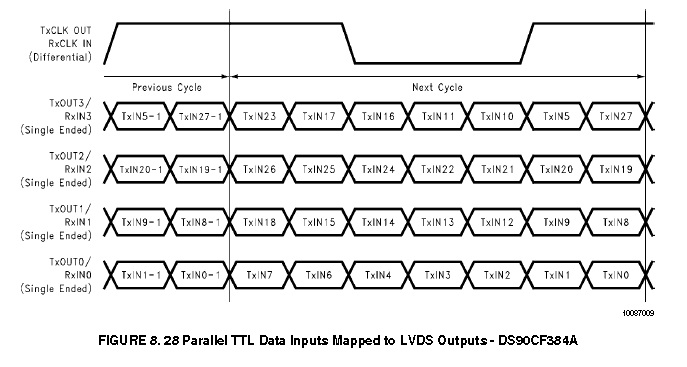
--- Quote Start --- Hello, i try to implement a system that displays either still color bars for use as a test pattern on a lvds tft panel. i use a Cyclone IV GX Eval board (EP4CGX150DF31) my idea is to split the systems in different unit Test Pattern Generator (VIP) --> Clocked Video Output (VIP) --> lvds serializer --> lvds video target (display) whereby the lvds serializer already works (i tested it in another design configuration), but test pattern generator makes some problems for debugging i the place the output signals (of the test pattern generator) to some output pins to check them on a scope, but the compiler reports that these pins stuck at VCC or GND. can someone explain whats wrong? best regards occino http://i43.tinypic.com/de1vg7.jpg (http://i43.tinypic.com/de1vg7.jpg) http://i43.tinypic.com/25z5rpg.jpg (http://i43.tinypic.com/25z5rpg.jpg) --- Quote End --- Hi, I Am working on a similar architecture, I have a LVDS LCD interface, I want to know whether we need to do any bitmapping for LVDS transfers. I have attached a snapshot of required serial data for all 4 channels. Please help me to understand.
Reply
Topic Options
- Subscribe to RSS Feed
- Mark Topic as New
- Mark Topic as Read
- Float this Topic for Current User
- Bookmark
- Subscribe
- Printer Friendly Page