- Mark as New
- Bookmark
- Subscribe
- Mute
- Subscribe to RSS Feed
- Permalink
- Report Inappropriate Content
Is any one having the datasheet of 16x2 lcd shipped from terasic. I bought the lcd with de1 but I did not get any manuals or datasheet. Can any one tell me how to interface or is there a datasheet available?:confused:
Link Copied
6 Replies
- Mark as New
- Bookmark
- Subscribe
- Mute
- Subscribe to RSS Feed
- Permalink
- Report Inappropriate Content
Use the Optrex manual as a reference:
http://www.optrex.com/pdfs/dmcman_full.pdf Lumex and Crytalfontz are the parts used by Terasic/Altera. These parts are compatible with the timing in the Optrex guide. warnings:
1) There are several pinouts for LCD modules, with some, the only difference is that the 5V and GND pins are swapped. So make sure you know which pins are which before you power the LCD. Try finding the part number on your module, eg., Lumex LCM-1602DSR/F-Y, and then go find the data sheet.
2) Do not interface to a non-5V compliant FPGA/CPLD directly. The LCD modules can drive the output bus to 5V for read accesses (this depends on the module and its configuration). Cheers, Dave
- Mark as New
- Bookmark
- Subscribe
- Mute
- Subscribe to RSS Feed
- Permalink
- Report Inappropriate Content
Thanks Dave,
I got a program from edaboard and i was working on that. The program is compatible with the data sheet that you suggested. As I download the .sof file the lcd display is fully fllled in a row. Please see the screenshots . http://2.bp.blogspot.com/-LY9gpOSyGFo/TacrWalpxtI/AAAAAAAAAXg/GLD8xrbU3Vw/s1600/P4130032.JPG Can any one find the problem? I tried changing the width for enable pulse. It is about 460ns now. What is the normal pulse width required? http://3.bp.blogspot.com/-nHRvpEu6D6U/TacrVju1LMI/AAAAAAAAAXc/aVh1Th0q--s/s1600/lcd+waveform.png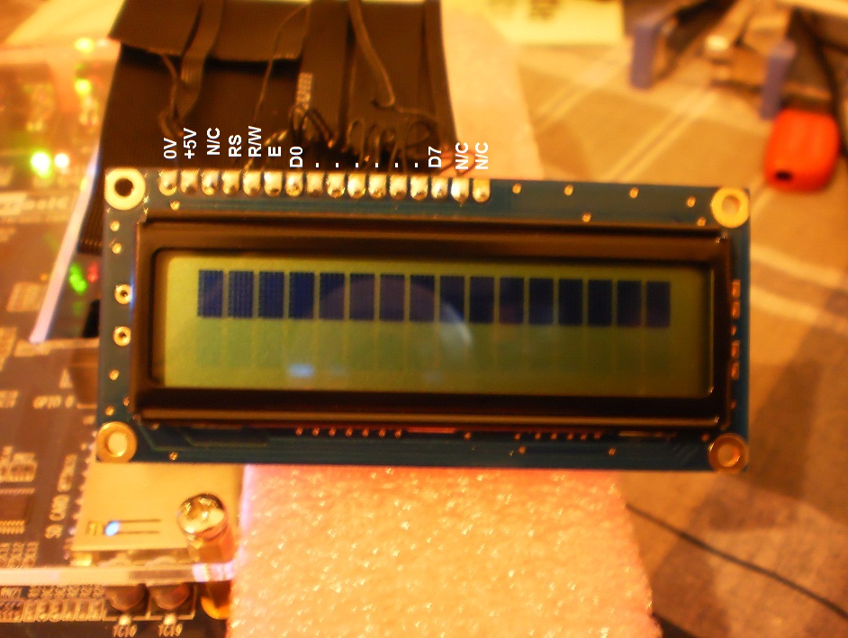
- Mark as New
- Bookmark
- Subscribe
- Mute
- Subscribe to RSS Feed
- Permalink
- Report Inappropriate Content
Its supposed to look like that when you turn the power on.
You now need to initialize the controller. The Optrex manual has the procedure. Cheers, Dave- Mark as New
- Bookmark
- Subscribe
- Mute
- Subscribe to RSS Feed
- Permalink
- Report Inappropriate Content
:)ya..its working the "8 - Bit Initialization" diagram was in the pdf u gave...
I didn't gave correct delays but still its working.. just need to adjust the background color intensity. Thanks Kiran- Mark as New
- Bookmark
- Subscribe
- Mute
- Subscribe to RSS Feed
- Permalink
- Report Inappropriate Content
--- Quote Start --- Hi Kiranjose! My apologies. Here are the data sheets for the LCD module that we sent to you. ;) --- Quote End --- :) thanks Allen
- Mark as New
- Bookmark
- Subscribe
- Mute
- Subscribe to RSS Feed
- Permalink
- Report Inappropriate Content
Reply
Topic Options
- Subscribe to RSS Feed
- Mark Topic as New
- Mark Topic as Read
- Float this Topic for Current User
- Bookmark
- Subscribe
- Printer Friendly Page