Transceiver Design Flow Level 2 - The Reconfiguration Controller
Success! Subscription added.
Success! Subscription removed.
Sorry, you must verify to complete this action. Please click the verification link in your email. You may re-send via your profile.
- Intel Community
- Intel Community Knowledge Base
- Product Support Forums Knowledge Base
- FPGA Knowledge Base
- FPGA Wiki
- Transceiver Design Flow Level 2 - The Reconfiguration Controller
Transceiver Design Flow Level 2 - The Reconfiguration Controller
- Subscribe to RSS Feed
- Mark as New
- Mark as Read
- Bookmark
- Subscribe
- Printer Friendly Page
- Report Inappropriate Content
Transceiver Design Flow Level 2 - The Reconfiguration Controller
Overview
This Level 2 article guides the user through the creation, instantiation, connection, and use of the Reconfiguration Controller as a part of a complete transceiver design. This article is a part of the complete Transceiver Design Flow series of articles.
Required Materials
- Quartus II 12.0 (preferably the latest official release) Understanding of the information contained in Transceiver Design Flow Level 1.
Documentation
- Intel® Stratix® Documentation - Use this for information on Stratix V device architecture.
- Transceiver Configurations in Stratix V Devices - Provides the transceiver channel datapath, clocking guidelines, channel placement guidelines, and a brief description of protocol features supported in each transceiver configuration for Stratix V devices.
- V-Series Transceiver PHY IP Core User Guide - Provides a general overview of the Altera IP core design flow to help you quickly get started with any Altera PHY IP core. The Altera IP Library is installed as part of
- the Quartus II installation process. You can select and parameterize any Altera IP core from the library using the MegaWizard in Quartus II.
- Avalon Specification - This document defines interfaces appropriate for streaming high-speed data, reading and writing registers and memory, and controlling off-chip devices.
- Dynamic Reconfiguration In Stratix V Devices - Refer to this document for technical information regarding using performing reconfiguration in Stratix V Devices.
What Is It?
The Reconfiguration Controller is a functional block in a transceiver design that is communicates to the Transceiver PHY IP as well as an Avalon MM Master. The controller dynamically reconfigures analog settings in Stratix V devices by writing to the Reconfiguration Control Space. Reconfiguration allows you to compensate for variations due to process, voltage, and temperature (PVT) in 28-nm devices. It is required for Stratix V devices that include transceivers. For more information, including technical details (in particular, how to interface the controller with the PHY IP), see Chapter 12 of the V-Series Transceiver PHY IP Core User Guide or this Application Note for a step-by-step example of using the Controller. Also, see the Dynamic Reconfiguration Guide for details on reconfiguration.
Generating The Reconfiguration Controller
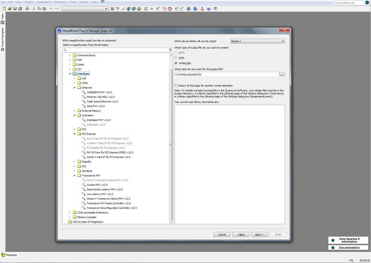
To generate the Reconfiguration Controller design files, open the MegaWizard Plugin Manager (see figure 1-1). Select "Create a new custom mega wizard variation" (see figure 1-2). Under the Interfaces > Transceiver PHY will be an option for Transceiver Reconfiguration Controller (see figure 1-3). Choose a name for the output files and click "Next." The next screen (figure 1-4) will display a block diagram of the controller with it's ports shown, and in this screen, you will be able to customize parameters for the controller. For an explanation of each parameter, see chapter 12 of the V-Series Transceiver PHY IP Core User Guide .
When finished entering your desired parameters, hit the "Finish" button.
Figure 1-1: Quartus MainScreen

Figure 1-2: Megawizard Main Screen
3/3e/Megawizard_Main_Screen.png

Figure 1-3: Choosing a PHY IP To Generate

Figure 1-4: Customizing the Parameters for the Reconfiguration Controller
/0d/Reconfiguration_Controller_Generation.png
At this point, there should be four new items in your project directory. Quartus generates a<phy_ip_instance_name> folder, a<phy_ip_instance_name_sim> folder,<phy ip instance name>.qip, and a phy_ip_instance_name.v. The folders contain lower level design files used in compilation, and the phy_ip_instance_name.v is the top level design file.
Connecting to the Transceiver PHY IP - The Reconfiguration Interface
The Interface that allows the Reconfiguration Controller to communicate with the Reconfiguration Control Space within the Transceiver PHY IP is known as the Reconfiguration Interface. The user must create the appropriate signals in the top-level module and connect the Transceiver PHY IP and the Reconfiguration Controller using these signals. It conforms to the Avalon MM Specification. See the Reconfiguration Interface sub-section of chapter 12 of the V-Series Transceiver PHY IP Core User Guide for a list and description of the signals that make up the interface.
Alternatively, if the user chooses to perform reconfiguration using a .mif file, the user can implement the MIF Reconfiguration Management Avalon MM Master Interface. See the MIF Reconfiguration Management Avalon MM Master Interface sub-section of chapter 12 of the Altera Transceiver PHY IP Core User Guide for a list and description of the signals that make up the interface. See the MIF sub-section of chapter 12 in the Transceiver PHY IP Core User Guide.
Connecting to the Avalon MM Master - The Reconfiguration Management Interface
The Reconfiguration Management Interface is a user-coded Avalon-MM slave interface that connects the Avalon MM Master to the Reconfiguration Interface. You can use an embedded controller to drive this interface. Alternatively, you can use a user coded finite state machine to control all Avalon-MM reads and writes to the Transceiver Reconfiguration Controller through this interface. This interface provides access to the Transceiver Reconfiguration Controller’s Avalon-MM registers. The interface must follow the Avalon MM Specification. See the Reconfiguration Management Interface sub-section of chapter 12 of the V-Series Transceiver PHY IP Core User Guide for a list and description of the signals that make up the interface.
Using the Reconfiguration Controller
The Transceiver Reconfiguration Controller provides two modes to dynamically reconfigure transceiver settings:
- Register Based—In this access mode you can directly reconfigure a transceiver PHY IP core using the Transceiver Reconfiguration Controller’s reconfiguration management interface. You initiate reconfiguration using a series of Avalon-MM reads and writes to the appropriate registers of the Transceiver Reconfiguration Controller. The Transceiver Reconfiguration Controller translates the device independent commands received on the reconfiguration management interface to device dependent commands on the transceiver reconfiguration interface. Each register-based feature has its own Avalon-MM address space within the Transceiver Reconfiguration Controller. See the Reconfiguration Controller Memory Map in Chapter 12 of the User Guide to describe the memory map that controls reconfiguration and signal integrity features.
- Streamer Based —This access mode allows you to either stream a MIF that contains the reconfiguration data or perform direct writes to perform reconfiguration. The streaming mode uses a memory initialization file (.mif) to stream an update to the transceiver PHY IP core. The .mif file can contain changes for many settings. For example, a single .mif file might contain changes to the PCS datapath settings, clock settings, and PLL parameters. You specify the .mif using write commands on the Avalon-MM PHY management interface. After the streaming operation is specified, the update proceeds in a single step. In the direct write mode, you perform Avalon-MM reads and writes to initiate a reconfiguration of the PHY IP. See the MIF sub-section of chapter 12 of the User Guide for details on writing a MIF file.
See Chapter 12 of the V-Series Transceiver PHY IP Core User Guide for more information.
Compilation in ModelSim
Compilation of the Reconfiguration Controller requires it's own library. Use the command vlib <library_name> to make a library. Navigate to the <phy_ip_instance_name_sim> folder and open the plain_files.txt that should have been generated upon completing the MegaWizard steps. The Reconfiguration Controller design files must be compiled in the order as they appear in the plain_files.txt file. To compile a design file use the command vlog <file_name>. if the design file is not in the same directory as your compilation .Tcl script, you must include the file path with the file name. For details on writing a compilation script for a Transceiver PHY design in ModelSim, see theTrasnceiver Design Flow Level 2 - Compilation In ModelSim article.
Key Words
Stratix V, PCIE PIPE PHY IP, Tranceiver Reconfiguration Controller, Physical layer, PCI Express, Express, Stratix Five, GT, GS, GX, Design, Example, guide, walkthrough,
PCIe, PCI E, PCI Express, Stratix V, SV, S, V, Walkthrough, guide, help, Stratix V GX, Stratix V GT, SV, SVGX, SVGT, S5GX, S5GT, S5, Stratix 5, Stratix 5 GX, StratixV, StratixV GX, Stratix5, Stratix5 GX, Altera, generated, generation, Instantiation, creation, design, files,
© 2010 Altera Corporation. The material in this wiki page or document is provided AS-IS and is not
supported by Altera Corporation. Use the material in this document at your own risk; it might be, for example, objectionable, misleading or inaccurate.
Community support is provided Monday to Friday. Other contact methods are available here.
Intel does not verify all solutions, including but not limited to any file transfers that may appear in this community. Accordingly, Intel disclaims all express and implied warranties, including without limitation, the implied warranties of merchantability, fitness for a particular purpose, and non-infringement, as well as any warranty arising from course of performance, course of dealing, or usage in trade.
For more complete information about compiler optimizations, see our Optimization Notice.