- 신규로 표시
- 북마크
- 구독
- 소거
- RSS 피드 구독
- 강조
- 인쇄
- 부적절한 컨텐트 신고
Hi Helpers!
I am working on a project in which i have to create 8:1 mux using 4:1 mux, I am done with the 4:1 code and then create symbol file which i used for making 8:1 mux .
4:1 code is mentioned in attachment.(If you find any error here please inform)
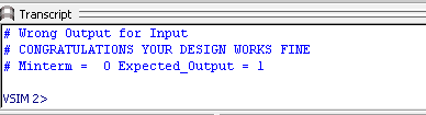
Problem is that when i run RTL Simulation Error occurs "WRONG OUTPUT FOR GIVEN INPUT" and i didn't get correct waveform .
Circuit Diagram is also attached!
May be i am not able to build the logic , Can someone help me in this case?
링크가 복사됨
- 신규로 표시
- 북마크
- 구독
- 소거
- RSS 피드 구독
- 강조
- 인쇄
- 부적절한 컨텐트 신고
Without seeing the testbench or the waveform, it's hard to figure out what's wrong here.
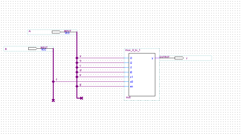
If A[2] is the enable signal, I'm not sure why you are inverting it going into the upper mux.
And your s0 line (D[2]) is disconnected from the upper mux in the schematic.
- 신규로 표시
- 북마크
- 구독
- 소거
- RSS 피드 구독
- 강조
- 인쇄
- 부적절한 컨텐트 신고
I am New to this coding area!
PLEASE help me clear my basics!
Suppose i have a 4:1 mux and have 4bit input i0,i1,i2,i3, (s0,s1)select lines and output Y.
I use two vcc pins A and B to connect with 4:1.
I want to know that when WE USE RTL Simulation It Give random values to the input and check expected output with the current output , It give random value to A and B or i0,i1,i2,i3.
Can anyone help me design or can anyone design 8:1 mux using 4:1 mux?
- 신규로 표시
- 북마크
- 구독
- 소거
- RSS 피드 구독
- 강조
- 인쇄
- 부적절한 컨텐트 신고
If you want to design 8:1 mux using 4:1 mux, perhaps the link below may helps.
Let me know if you need further help with this circuit design.
https://www.tutorialspoint.com/digital_circuits/digital_circuits_multiplexers.htm

- 신규로 표시
- 북마크
- 구독
- 소거
- RSS 피드 구독
- 강조
- 인쇄
- 부적절한 컨텐트 신고
@RichardTanSY_Altera I want to build 8:! mux using only 4:1 mux and i tried everything but always error occur:(
- 신규로 표시
- 북마크
- 구독
- 소거
- RSS 피드 구독
- 강조
- 인쇄
- 부적절한 컨텐트 신고
First, you might need to check your design whether it is designed correctly. Like what Strell mentioned, the D2 wire is not connected to s0 in the first 4 mux. Is this expected? Then, check whether the testbench is write correctly.

Are you simulate using Modelsim? Seems to me, "Wrong output to input" error is generated from your testbench and most probably due to design issue, as you got an unexpected output.
You mentioned there is no wave window, have you try to simulate using the flow below, by adding Signals To Wave Window?
https://www.intel.com/content/dam/www/programmable/us/en/pdfs/literature/ug/ug_gs_msa_qii.pdf
- 신규로 표시
- 북마크
- 구독
- 소거
- RSS 피드 구독
- 강조
- 인쇄
- 부적절한 컨텐트 신고
@RichardTanSY_Altera Ok Let's start from the beginning! Can you help mw with this project?
1- I code for 4:1 mux please check if you find something wrong! (Code complied successfully)
2-I made a symbol file for 4:1 mux and then give Two inputs A and B .
3-But when is use university program vmf method to check my design error occurs.
All screen shot are provided below.
And last this is i didn't know how to connect A and B with the 4:1 mux i just did random connections as i didn't understand the logic behind connecting 2 bits input with 4 bits input so if you also find something wrong there then please correct me.
- 신규로 표시
- 북마크
- 구독
- 소거
- RSS 피드 구독
- 강조
- 인쇄
- 부적절한 컨텐트 신고
Well, now your design doesn't make any sense at all. You have that "A" bus input and you're creating signals off of A that are lowercase letters. That doesn't make any sense. Your initial design, as I stated, was close to what you needed to do. The 4-to-1 mux itself looks fine.
And since you still have not shared the simulation testbench (the sequence of inputs into the design for the simulation), it's still not possible to figure out why you're getting an error (thought that changed design would explain the more recent problems).