- Mark as New
- Bookmark
- Subscribe
- Mute
- Subscribe to RSS Feed
- Permalink
- Report Inappropriate Content
Hi all,
I have a design where I generate an SPI clock and send some data over the slave. The slave is an ADC with its own setup/hold time constraints. In these constraints, the slave data input SDI has constraints with respect to the SCLK, but I'm not sure how to properly constraint that. What I did so far is that I constrainted the SCLK on its own as if it's a data output of the FPGA and then constraint the MOSI with referencing the SCLK. The syntax I used in the sdc file is added below.
# main clock of the FPGA
create_clock -name {clk} -period 100MHz [get_ports {clk}]
# Specify generated clock from PLL (PLL output is 100MHz)
# set_instance_assignment -name corepll_inst|altpll_component|auto_generated|pll1 -to pll_inst
# create_generated_clock -name {pll_clk} -source [get_pins pll_inst|clk[0]] -divide_by 1
# constraints for SCLK and MOSI
set_output_delay -clock {corepll_inst|altpll_component|auto_generated|pll1|clk[0]} -max 3 [get_ports {SCLK1}]
set_output_delay -clock {corepll_inst|altpll_component|auto_generated|pll1|clk[0]} -min -2 [get_ports {SCLK1}]
set_output_delay -clock {corepll_inst|altpll_component|auto_generated|pll1|clk[0]} -reference_pin SCLK1 -max 5 [get_ports {MOSI1}]
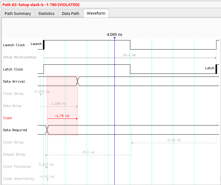
set_output_delay -clock {corepll_inst|altpll_component|auto_generated|pll1|clk[0]} -reference_pin SCLK1 -min -5 [get_ports {MOSI1}]What I observe in the Timing Analyzer is that the setup and hold times are not the only things when checking the timing analyzer. For the example that you can see on the snippet attached, I would expect that the data required for the setup time of SCLK1 would be only 3 ns far from the latch clock's posedge, where the cursor is. I'm almost sure that what I want to achieve does not match with the constraints I used, therefore I'd like to ask what I'm doing wrong or missing.
Any help is much appreciated,
Cheers

Link Copied
- Mark as New
- Bookmark
- Subscribe
- Mute
- Subscribe to RSS Feed
- Permalink
- Report Inappropriate Content
Can you show the detailed path breakdown and more of your timing constraints? It's not clear why data is being launched on a falling clock edge in this analysis.
- Mark as New
- Bookmark
- Subscribe
- Mute
- Subscribe to RSS Feed
- Permalink
- Report Inappropriate Content
Hi,
I cannot show more of my timing constraints because there is simply nothing else...
But please see the pictures attached for the detailed paths and the corresponding waveform
- Mark as New
- Bookmark
- Subscribe
- Mute
- Subscribe to RSS Feed
- Permalink
- Report Inappropriate Content
What are the latch and launch clk, are they the same clk?
- Mark as New
- Bookmark
- Subscribe
- Mute
- Subscribe to RSS Feed
- Permalink
- Report Inappropriate Content
The PLL clock is used for the whole design, the design has only one clock domain.
- Mark as New
- Bookmark
- Subscribe
- Mute
- Subscribe to RSS Feed
- Permalink
- Report Inappropriate Content
So you are clocking the external device with an output clock, basically source synchronous. You need a generated clock constraint targeted to the output and the output port for that clock should have a false path constraint so it is not being analyzed as a data output. You should not perform a data analysis on a clock output. So for example:
#not sure why this was commented out and incomplete unless you were trying to create a virtual clock and is it SCLK1 or SCLK2 out?
create_generated_clock -name {sclk1_clk} -source [get_pins pll_inst|clk[0]] [get_ports {SCLK1}] -divide_by 1
set_false_path -to [get_ports {SCLK1}]
#-reference_pin was incorrect here; delay values could simply be Tsu for max and -Th for min if clock and data traces on board are matched delay
set_output_delay -clock sclk1_clk -max 5 [get_ports {MOSI1}]
set_output_delay -clock sclk1_clk -min -5 [get_ports {MOSI1}]
- Mark as New
- Bookmark
- Subscribe
- Mute
- Subscribe to RSS Feed
- Permalink
- Report Inappropriate Content
Hi @sstrell ,
This way I do not get any setup/hold time violations but I am still not fully convinced if this is the way to go. When I report clocks / clock tree, I do not see the virtual clocks "pll_clk" (yes, I uncommented those lines) and "sclk1_clk" in any of those reports. In addition, I do see that the 'create_generated_clock' commands for these two virtual clocks are also reported to be ignored constraints in the Timing Analyzer. Same goes for the miso1/mosi1 constraints, I can see them under Ignored Constraints as well. So what I did in my .sdc file is as follows:
#**************************************************************
# Time Information
#**************************************************************
set_time_format -unit ns -decimal_places 3
#**************************************************************
# Create Clock
#**************************************************************
create_clock -name {clk} -period 100MHz [get_ports {clk}]
create_clock -name altera_reserved_tck  -period 24.000MHz [get_ports altera_reserved_tck]
#**************************************************************
# Generated clocks
#**************************************************************
derive_pll_clocks
derive_clock_uncertainty
# Specify generated clock from PLL (PLL output is 100MHz)
set_instance_assignment -name corepll_inst|altpll_component|auto_generated|pll1 -to pll_inst
create_generated_clock -name {pll_clk} -source [get_pins pll_inst|inclk0] [get_pins pll_inst|clk0] -divide_by 1
# create SPI clocks of 50MHz
create_generated_clock -name {sclk1_clk} -source [get_pins pll_inst|clk[0]] [get_ports {SCLK1}] -divide_by 2
set_false_path -from * -to [get_ports {SCLK1}]

set_input_delay  -clock {sclk1_clk} -max  4  [get_ports {MISO1}]
set_input_delay  -clock {sclk1_clk} -min  2  [get_ports {MISO1}]
set_output_delay -clock {sclk1_clk} -max  5  [get_ports {MOSI1}]
set_output_delay -clock {sclk1_clk} -min -5  [get_ports {MOSI1}]
I don't know if that makes any difference here but I'm using Quartus Standard Version 21.1. Not sure what I'm missing here in the sdc...
- Mark as New
- Bookmark
- Subscribe
- Mute
- Subscribe to RSS Feed
- Permalink
- Report Inappropriate Content
Hi there could you provide all the files of the project, and you can exclude you RTL(.v file) for confidentiality.
- Mark as New
- Bookmark
- Subscribe
- Mute
- Subscribe to RSS Feed
- Permalink
- Report Inappropriate Content
There you go! Please let me know if you need anything else.
In short, I added virtual clocks for the QSPI and SCLK1-6 outputs and added them in the same clock group with the pll clock in addition to what I've discussed with the user sstrell above
- Mark as New
- Bookmark
- Subscribe
- Mute
- Subscribe to RSS Feed
- Permalink
- Report Inappropriate Content
[content removed]
- Mark as New
- Bookmark
- Subscribe
- Mute
- Subscribe to RSS Feed
- Permalink
- Report Inappropriate Content
Hi @RichardTanSY_Intel ,
The design is already pipelined. But what I wanted to achieve mainly is to learn how to properly set constraints for a design like mine, not making the design more "timing-friendly". So it would be great if you can help me with that, so that I can see whether my design is good or I need adjustments on the RTL.
- Mark as New
- Bookmark
- Subscribe
- Mute
- Subscribe to RSS Feed
- Permalink
- Report Inappropriate Content
Hi @anonimcs
I attempted to remove my original post content as I mistakenly posted my response in the wrong forum case. However, it seems you can still see it. Please kindly ignore my previous post.
Regarding your issue, if you're okay with sharing your RTL, could you archive the .qar project (Project > Archive Project) so that I can investigate it further? The project_files.zip file doesn't seem to be compilable.
Additionally, could you provide the block diagram of your design?
This will help me understand the overall picture and which path you're trying to constrain.
Regards,
Richard Tan
- Mark as New
- Bookmark
- Subscribe
- Mute
- Subscribe to RSS Feed
- Permalink
- Report Inappropriate Content
If you can give me your email address, I can generate and send you my .qar file.
- Mark as New
- Bookmark
- Subscribe
- Mute
- Subscribe to RSS Feed
- Permalink
- Report Inappropriate Content
- Mark as New
- Bookmark
- Subscribe
- Mute
- Subscribe to RSS Feed
- Permalink
- Report Inappropriate Content
- Mark as New
- Bookmark
- Subscribe
- Mute
- Subscribe to RSS Feed
- Permalink
- Report Inappropriate Content
Hi there, is there any progress on that?
- Mark as New
- Bookmark
- Subscribe
- Mute
- Subscribe to RSS Feed
- Permalink
- Report Inappropriate Content
Hi, not yet. Waiting for @RichardTanSY_Intel 's response after a few emails between us.
- Mark as New
- Bookmark
- Subscribe
- Mute
- Subscribe to RSS Feed
- Permalink
- Report Inappropriate Content
May I know what's your main concern now. I may help the following supports.
- Mark as New
- Bookmark
- Subscribe
- Mute
- Subscribe to RSS Feed
- Permalink
- Report Inappropriate Content
Could you send me an email (and the link for uploading the .qar file again if you cannot access the files that I uploaded for Richard) ? I can just forward the emails to you.
- Mark as New
- Bookmark
- Subscribe
- Mute
- Subscribe to RSS Feed
- Permalink
- Report Inappropriate Content
I see, I have got the email from Richard. If there is no more changes on the project in the email, I'll use this one for investigation.
- Mark as New
- Bookmark
- Subscribe
- Mute
- Subscribe to RSS Feed
- Permalink
- Report Inappropriate Content
No, there are no updates since my email on 8th of May. Please go ahead!
- Subscribe to RSS Feed
- Mark Topic as New
- Mark Topic as Read
- Float this Topic for Current User
- Bookmark
- Subscribe
- Printer Friendly Page