- Mark as New
- Bookmark
- Subscribe
- Mute
- Subscribe to RSS Feed
- Permalink
- Report Inappropriate Content
Hi,
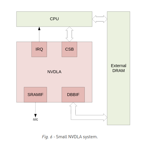
I am trying integerate NVDLA , NVIDIA's deep learning accelerator, on FPGA. My end goal is to implement the given system in nvdla_system.png, using platform designer.
/home/shazib/Qazi_document/Coursera/nvdla_system.png
For intergration the nvdla in platform designer, I am thinking of including the nvdla core in platform designer as a new component. To do that I need to define the DBBIF (Data Backbone Interface as AXI master).
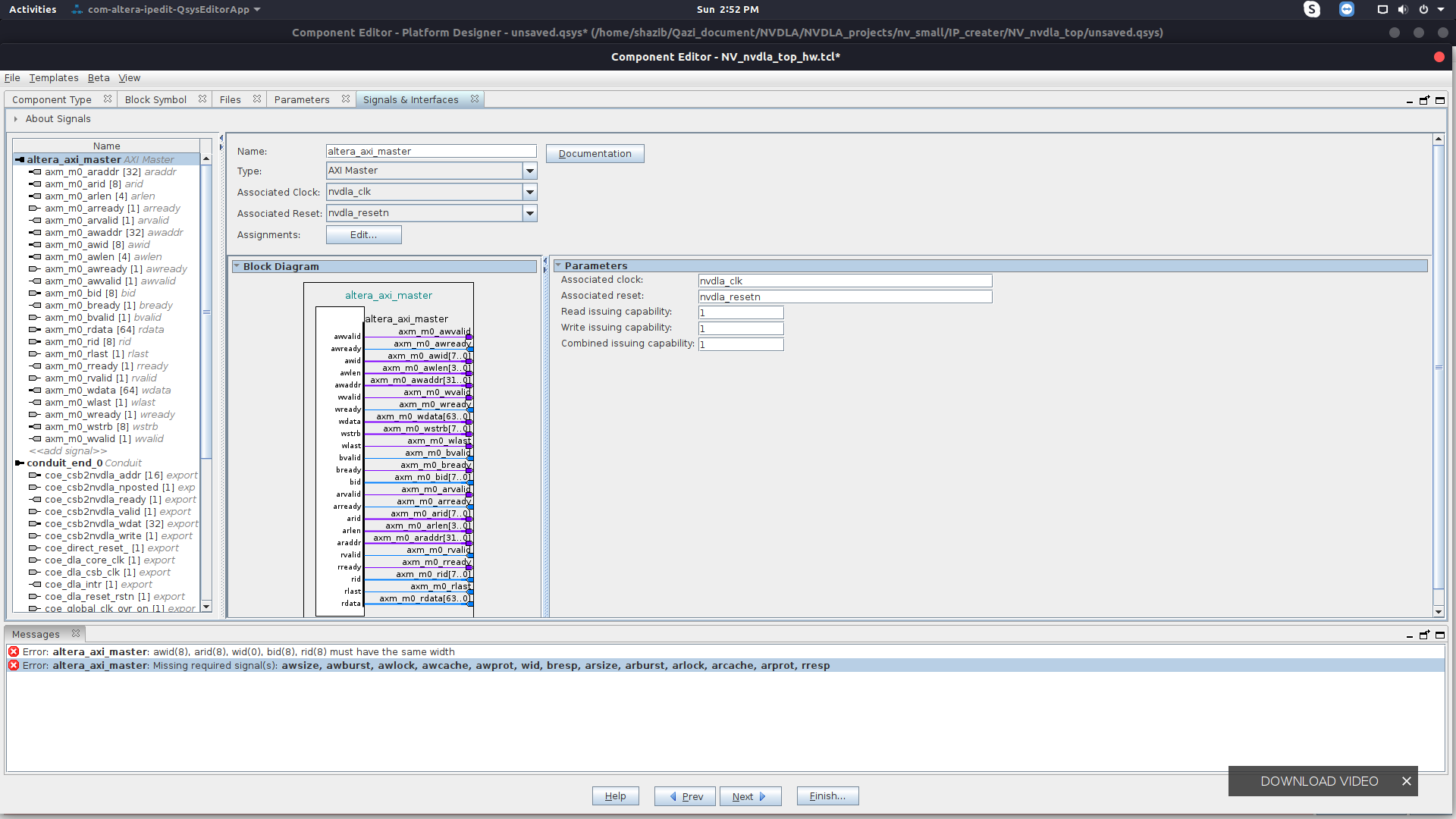
I have tried to make a new component by declaring the DBBIF as AXI master but I am getting the errors given in the image file named error.png.
/home/shazib/Qazi_document/Coursera/error.png
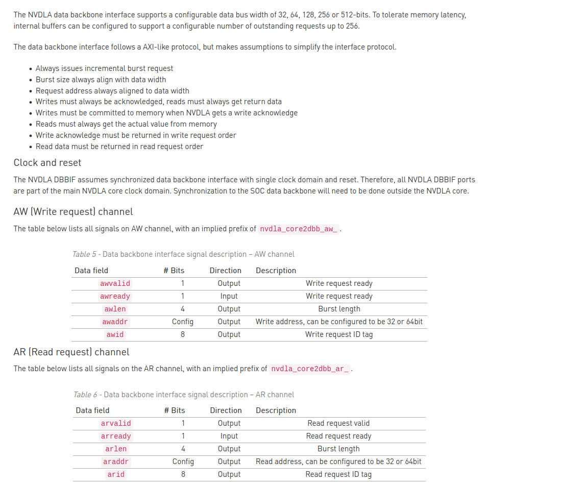
The specification for AXI interface used in NVDLA are given the AXI_specificaion.png
/home/shazib/Qazi_document/Coursera/AXI_specification0.png
/home/shazib/Qazi_document/Coursera/AXI_specification1.png
Actually some the axi protocol signal are not being used in NVDLA and explanation for that is given in the nvdla_axi_assumptions.png
/home/shazib/Qazi_document/Coursera/nvdla_axi_assumptions.png
any help in this regard will be appreciated.
- Mark as New
- Bookmark
- Subscribe
- Mute
- Subscribe to RSS Feed
- Permalink
- Report Inappropriate Content
What you've attached are just changes to the standard AXI behaviors, not specific signal roles. As you've found with the Component Editor, you must have certain signals and some at matching bus widths to follow the protocol for it to work as a custom component with an AXI interface.
Use the template to add all the signals in to your design and work from there. Platform Designer will only work with the true standard interface and the normal way that the signals are supposed to work, so "AXI-like" behavior wouldn't work unless you customize your component's logic to work with this (instead of relying on the interconnect to do it for you).
You say you're not familiar enough with AXI, but from looking at this, I think you may need get more information about the standard for yourself to make this work.
Link Copied
- Mark as New
- Bookmark
- Subscribe
- Mute
- Subscribe to RSS Feed
- Permalink
- Report Inappropriate Content
- Mark as New
- Bookmark
- Subscribe
- Mute
- Subscribe to RSS Feed
- Permalink
- Report Inappropriate Content
The errors are pretty self-explanatory, aren't they? Bit widths and missing signals.
I don't know how you're setting up the signals and interfaces (from existing HDL code or manually), but if you select a template from the Templates menu there at the top of the Component Editor, you're guaranteed to have all the signals you need.
If you have existing HDL code, you would then need to add the code to the component on the Files tab, analyze the HDL files there as well, and then map the ports in the code to interfaces and signals on that tab.
- Mark as New
- Bookmark
- Subscribe
- Mute
- Subscribe to RSS Feed
- Permalink
- Report Inappropriate Content
Actually, I am trying to port NVDLA Architecture on FPGA. NVDLA has implemented an AXI like master interface to communicate with DRAM directly.
By "AXI like" I mean that few signals of AXI protocol are not implemented in and explanation for that is given in the nvdla_axi_assumptions.png file attached below. I don't have enough knowledge about AXI-protocol to understand the assumption given in the .png file.
@sstrell Could please go through the nvdla_axi_assumptions.png file and guide me on how to declare the logic for missing signals based on the information given in the file.
- Mark as New
- Bookmark
- Subscribe
- Mute
- Subscribe to RSS Feed
- Permalink
- Report Inappropriate Content
What you've attached are just changes to the standard AXI behaviors, not specific signal roles. As you've found with the Component Editor, you must have certain signals and some at matching bus widths to follow the protocol for it to work as a custom component with an AXI interface.
Use the template to add all the signals in to your design and work from there. Platform Designer will only work with the true standard interface and the normal way that the signals are supposed to work, so "AXI-like" behavior wouldn't work unless you customize your component's logic to work with this (instead of relying on the interconnect to do it for you).
You say you're not familiar enough with AXI, but from looking at this, I think you may need get more information about the standard for yourself to make this work.
- Subscribe to RSS Feed
- Mark Topic as New
- Mark Topic as Read
- Float this Topic for Current User
- Bookmark
- Subscribe
- Printer Friendly Page