- Mark as New
- Bookmark
- Subscribe
- Mute
- Subscribe to RSS Feed
- Permalink
- Report Inappropriate Content
Hi,
I've a question about the Quartus attribute for synchronisation:
attribute altera_attribute of sync_s : signal is "-name SYNCHRONIZER_IDENTIFICATION FORCED_IF_ASYNCHRONOUS";
- Mark as New
- Bookmark
- Subscribe
- Mute
- Subscribe to RSS Feed
- Permalink
- Report Inappropriate Content
Hi,
You may take a look into this https://www.youtube.com/watch?v=VbL_eflvHM4
It provide details on how you should handle the CDC path, let us know if there are more question base on the video.
Best regards,
Kenny Tan
Link Copied
- Mark as New
- Bookmark
- Subscribe
- Mute
- Subscribe to RSS Feed
- Permalink
- Report Inappropriate Content
Have you read this page:
In particular the note" "as long as the Optimize Design for Metastability option is turned on. " below the table is relevant.
Typically for crossing an asynchronous boundary you will have a register clocked on clock A driving a net to a dual rank pair of registers in sequence clocked on clock B. You will only use the output of the second register in the clock B domain.
It is also the case that checking the timing between the registers on clock A vs the registers on clock B, where clocks A and B are asynchronous, is not meaningful. Normally you would use the set_clock_groups -asynchronous -group {ClockA} -group {ClockB} directive to inform the timing analyzer the clocks are unrelated and timing can't be checked.
- Mark as New
- Bookmark
- Subscribe
- Mute
- Subscribe to RSS Feed
- Permalink
- Report Inappropriate Content
Thanks for your reply!
Yes I have set the setting for metastability. Furthermore I've set "forced if async" to detect clock domain crossing.
I just want to sync a status signal which goes from 1 to 0 or 0 to 1 for a long time!
There is no data sync for that I obviously would use a CDC FIFO!
Due I use 3 sync stages there should be no issue with metastability after synchronisation, I guess.
Are there further constraints required like explained in following page? https://www.intel.com/content/www/us/en/programmable/support/support-resources/knowledge-base/tools/2017/how-do-i-constrain-my-clock-domain-crossing-.html?wapkw=%20How%20do%20I%20constrain%20my%20clock%20domain%20crossing?
I think false_path is not recommended anymore.
As mentioned in page above "Next, constrain the paths with set_net_delay to make them as short as possible":
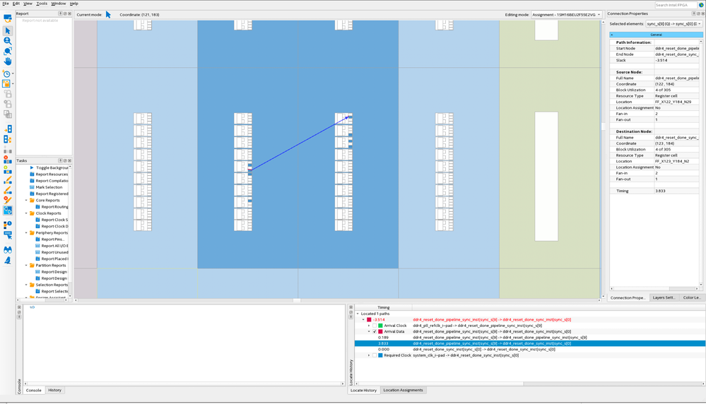
Would this has any further positive effects in placing both registers close to each other? (Like in my screenshot from chip planer) Or will this be done by synchroniser detection automatically?
(Like "ASYNC_REG" attribute used by Xilinx to force both regs placed close to each other)
Do I have to define skew & net delay, too, even if the synchroniser detection is "on" for async clock domains?
Sorry for all my questions but I want to be sure no issues will come up and I am quite new to Intel FPGAs (just worked with Xilinx FPGAs for now).
- Mark as New
- Bookmark
- Subscribe
- Mute
- Subscribe to RSS Feed
- Permalink
- Report Inappropriate Content
Hi,
You may take a look into this https://www.youtube.com/watch?v=VbL_eflvHM4
It provide details on how you should handle the CDC path, let us know if there are more question base on the video.
Best regards,
Kenny Tan
- Mark as New
- Bookmark
- Subscribe
- Mute
- Subscribe to RSS Feed
- Permalink
- Report Inappropriate Content
Thanks for the video link! Very well explained!
Is it possible to write net_delay SDC command in HDL as attribute?
Best regards
- Mark as New
- Bookmark
- Subscribe
- Mute
- Subscribe to RSS Feed
- Permalink
- Report Inappropriate Content
nope, you can check all the attribute by right click the verilog/vhdl files -> insert template.
- Mark as New
- Bookmark
- Subscribe
- Mute
- Subscribe to RSS Feed
- Permalink
- Report Inappropriate Content
Since this thread had been answered, we shall close this thread. If you still need further assistance, you are welcome to post a response within 15days or open a new thread, some one will be right with you.
- Subscribe to RSS Feed
- Mark Topic as New
- Mark Topic as Read
- Float this Topic for Current User
- Bookmark
- Subscribe
- Printer Friendly Page