- Mark as New
- Bookmark
- Subscribe
- Mute
- Subscribe to RSS Feed
- Permalink
- Report Inappropriate Content
I am porting an old NIOS II design from Quartus II 12.1 with SOPC Builder to Quartus Prime 20.1 Standard with Platform Designer.
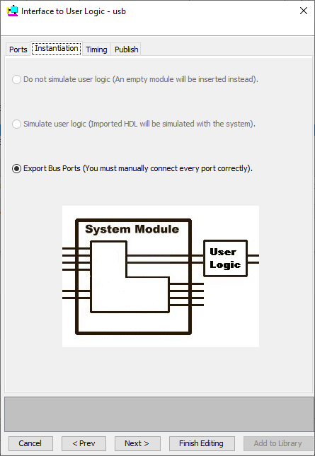
In our old design we have a few "Interface to User Logic" components, more precisely, "Avalon Register Slaves".
Can anyone tell me what the equivalents are in Platform Designer? or how to migrate these components?
Link Copied
- Mark as New
- Bookmark
- Subscribe
- Mute
- Subscribe to RSS Feed
- Permalink
- Report Inappropriate Content
Are they memories? Exported connections? Can you show a screenshot of what you are referring to?
- Mark as New
- Bookmark
- Subscribe
- Mute
- Subscribe to RSS Feed
- Permalink
- Report Inappropriate Content
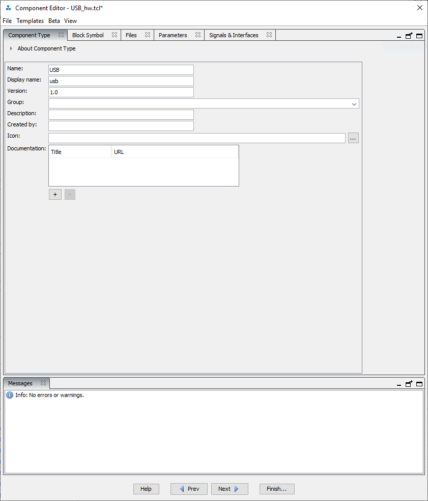
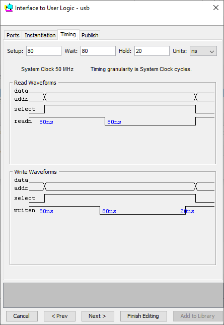
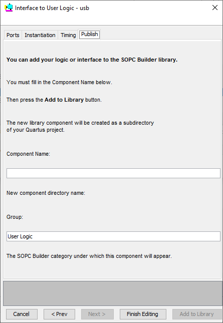
I have attached screenshots from the old component in SOPC Builder, the signals are defined in the top file. My question is how to replicate this in Platform Designer?


- Mark as New
- Bookmark
- Subscribe
- Mute
- Subscribe to RSS Feed
- Permalink
- Report Inappropriate Content
You can refer to page 282 of below document:
- Mark as New
- Bookmark
- Subscribe
- Mute
- Subscribe to RSS Feed
- Permalink
- Report Inappropriate Content
I have now looked at the document, and it does not help me migrate from an old SOPC project to a platform designer project. I really do not understand how to extract the relevant information from the old SOPC modules, which seems to know things magically, to replicate them in my Platform Designer project. In Plaform Designer things have changed, names and features have disappeared, and I'm sorry to say, the "support" here is not that helpful in getting my task done. Is there any way to call or e-mail Intel directly?
- Mark as New
- Bookmark
- Subscribe
- Mute
- Subscribe to RSS Feed
- Permalink
- Report Inappropriate Content
Is this your own custom component? If so, use the Component Editor (accessed from the IP Catalog in Platform Designer), which is basically a wizard, to point to your HDL file(s) and set up the interface(s) (Avalon slave as you mention, which is now referred to as an "agent" interface in the newest versions of the software).
- Mark as New
- Bookmark
- Subscribe
- Mute
- Subscribe to RSS Feed
- Permalink
- Report Inappropriate Content
Thanks for the reply!
Yes, the components(there are 5 different) were made by a colleague of mine, ten years ago, they only appear as interface to user logic, and a .vhd file.
I tried going through a component, but there are some discrepancies where I am not sure what to do exactly.
E.g. I have a component where the data is inout, but I have to do a separate read and write data line in Platform Designer, I'll try to attach some screenshots of the component from SOPC and my try of implementing it in PD.
Bear with me, I am a novice at Quartus, and a bit under time pressure
- Mark as New
- Bookmark
- Subscribe
- Mute
- Subscribe to RSS Feed
- Permalink
- Report Inappropriate Content
Is the data accessed by the system or is it used outside of the system? If it's going outside, it should be a conduit interface that gets exported from the system. Your vhd_snip image doesn't show the data or how it's used.
There's no bidirectional logic in the core of an FPGA so if it is a bidirectional interface, the bidirectional logic is implemented in the I/O cell, not in the system or FPGA fabric.
- Mark as New
- Bookmark
- Subscribe
- Mute
- Subscribe to RSS Feed
- Permalink
- Report Inappropriate Content
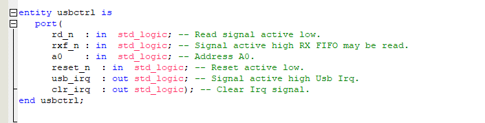
I have attached the complete .vhd file.
In SOPC_1.png data is shown as inout direction, I was just wondering how to mirror this in PD, and if my solution in PD_5.png was the right method.
- Mark as New
- Bookmark
- Subscribe
- Mute
- Subscribe to RSS Feed
- Permalink
- Report Inappropriate Content
The component you've created in the Component Editor doesn't match your code or the old design (and the code doesn't match the old design either so this is doubly confusing).
Assuming the code you've attached is what you want to use to create a component, do this:
1) Open Component Editor and create a new component on the Component Type tab.
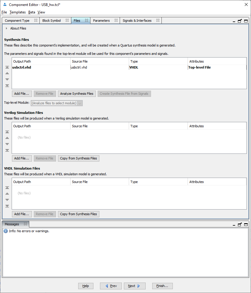
2) Add the .vhd file on the Files tab and click Analyze Synthesis Files.
3) On the Signals and Interfaces tab, keep the reset and interrupt sender interfaces you have in your screenshot. Those are correct. There is no clock so don't create a clock interface (though there should be a clock in every Platform Designer component).
4) Create an Avalon agent (slave) interface with the following signal roles for the signals in your design: rd_n is read_n, clr_irq is readdata, and a0 is address. rxf_n does not conform to any of the Avalon signal roles that I can think of, so you may want to put that in its own separate conduit interface. This is the best mapping I can think of based on your design. Do not add any additional signals on that tab. You have to use the signals that are the ports of your design.
I'm not even sure if this will work because there is no clock. It may make more sense to just implement this outside the Platform Designer system and use exported interfaces to make connections to it.
If you're not familiar with any of this, I'd recommend watching some training videos:
https://www.intel.com/content/www/us/en/programmable/support/training/course/oqsys3000.html (look for the part about the Component Editor)
https://www.intel.com/content/www/us/en/programmable/support/training/course/opdstdint.html
There are other training modules for the basics of using Platform Designer itself.
- Mark as New
- Bookmark
- Subscribe
- Mute
- Subscribe to RSS Feed
- Permalink
- Report Inappropriate Content
I found a solution, by converting the old SOPC project to QSYS in Quartus II 12.1, and adding the modules in 20.1 as the conversion suggested;
The modules work, when they are added as "Generic Tri-State Controller" and the Signals are configured as suggested in the conversion, no need for .vhd files, or anything else.
- Subscribe to RSS Feed
- Mark Topic as New
- Mark Topic as Read
- Float this Topic for Current User
- Bookmark
- Subscribe
- Printer Friendly Page