- Mark as New
- Bookmark
- Subscribe
- Mute
- Subscribe to RSS Feed
- Permalink
- Report Inappropriate Content
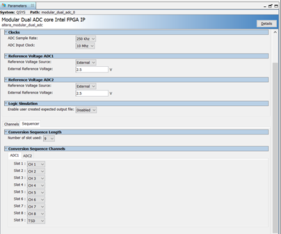
We are using the part 10M50DAF256I76 in one of our designs. In this design we are using the available on chip modular dual ADC. The interface for the ADC is generated inside QSYS with the following settings as shown in the images below. The ADC IP is operating at 100 MHz and the ADC PLL is set to operate at 10MHz. We are using the tool Quartus Prime Version 18.1.0 SJ Standard edition to build our design.
With certain builds we find the on-chip ADC getting hanged on bootup. We did add STP to the signals present inside the ADC IP block and observed that FSM inside altera_adc_control for ADC1 after exiting the state PWRUP_CH (refer the image below) doesn’t enter any of the other states inside the FSM. It is also evident from the STP capture that sync ready and clk_dft_hl is high before the FSM exits PWRUP_CH so as per the logic mentioned in altera_modular_adc_control_fsm.v the FSM is supposed to transition to the state PWRUP_SOC. Another important point to note is that from the STP it is observed that while the FSM was in PWRUP_CH state, tsen input was high meaning the TSD channel of the ADC 1 is being sampled.
Requesting you to help us in debugging further as to why it is not entering the any of the FSM state after exiting PWRUP_CH and let us know why it appears only in certain Quartus build.
In-case the images are not clear, please refer to the word document attached with this post.
Link Copied
- Mark as New
- Bookmark
- Subscribe
- Mute
- Subscribe to RSS Feed
- Permalink
- Report Inappropriate Content
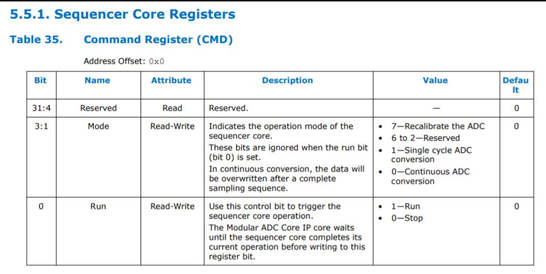
Are you saying it's stuck when you're in continuous ADC conversion mode? What mode are you using or are you just setting the run bit (overriding the mode option)?
- Mark as New
- Bookmark
- Subscribe
- Mute
- Subscribe to RSS Feed
- Permalink
- Report Inappropriate Content

- Mark as New
- Bookmark
- Subscribe
- Mute
- Subscribe to RSS Feed
- Permalink
- Report Inappropriate Content
If you're setting bit 0 to 1 (the run bit), as stated in that table, that overrides the single cycle mode. If you want single cycle, the register should be set to 0x2 (run bit set to 0).
- Mark as New
- Bookmark
- Subscribe
- Mute
- Subscribe to RSS Feed
- Permalink
- Report Inappropriate Content
Does this means that we should never set the "run bit" to "1" in single cycle conversion mode?
OR
Should we first write 0x02 to CMD register, wait for a delay of approx. 1ms, and then set "run bit" to "1" in single cycle conversion mode i.e. write 0x03 to CMD Register
- Mark as New
- Bookmark
- Subscribe
- Mute
- Subscribe to RSS Feed
- Permalink
- Report Inappropriate Content
If you use a mode other than continuous (mode set to 0x0), you don't use the run bit. I'm not 100% certain on this, but that's the impression I get from the chart.
- Mark as New
- Bookmark
- Subscribe
- Mute
- Subscribe to RSS Feed
- Permalink
- Report Inappropriate Content
What is the frequency of the clock port? Is the timing analysis clean, without any negative slack?
For the run bit, it is used to start the ADC conversion. For Single cycle mode, this bit should be set by the user to start the conversion. After conversion finishes for the last slot, the IP clears it. Refer Table 8 in the following link: Intel MAX 10 Analog to Digital Converter User Guide
- Mark as New
- Bookmark
- Subscribe
- Mute
- Subscribe to RSS Feed
- Permalink
- Report Inappropriate Content
What is the frequency of the clock port? ADC IP is operating at 100 MHz and the ADC PLL is set to operate at 10MHz.
Is the timing analysis clean, without any negative slack? NO, there are no timing error related to ADC IP or ADC Driver.
Like you said we are setting the ADC Command Register to 0x03 i.e.
Mode = Single cycle mode
Run Bit = true
- Mark as New
- Bookmark
- Subscribe
- Mute
- Subscribe to RSS Feed
- Permalink
- Report Inappropriate Content
Hi Sagar,
Looking at the waveform that you have shared, clk_dft signal frequency does not seems to be right. It should be 250KHz (4000 ns) which is your ADC sample rate in the IP wizard. From the waveform it definitely not near to that frequency.
Please check the freq of clk_dft in a working build.
Make sure that the clock to the ADC PLL i.e. 10 MHz is stable and has no noise.
Also monitor if the reset_sink_reset_n and adc_pll_locked_export to the IP are constantly set to high.
Regards
- Mark as New
- Bookmark
- Subscribe
- Mute
- Subscribe to RSS Feed
- Permalink
- Report Inappropriate Content
We do not receive any response from you to the previous answer that I have provided. This thread will be transitioned to community support. If you have a new question, feel free to open a new thread to get the support from Intel experts. Otherwise, the community users will continue to help you on this thread. Thank you
- Subscribe to RSS Feed
- Mark Topic as New
- Mark Topic as Read
- Float this Topic for Current User
- Bookmark
- Subscribe
- Printer Friendly Page


