- Mark as New
- Bookmark
- Subscribe
- Mute
- Subscribe to RSS Feed
- Permalink
- Report Inappropriate Content
I'm having some trouble analyzing a low speed ripple clock. The original design incorporated a low frequency ripple clock which I believe had timing errors in the hardware. I now want to change the ripple clock to a clock enable and I believe the timing will be fixed. But before I do that, I would like to see TimeQuest show the timing errors in the old ripple clock design for confidence that it really was a problem.
Please see attatched image file. I believe the timing errors should occur because in Process B the data is clocked in only using a very low speed ripple clock with. I am guessing the delays because of the divide by 4000 creates long delays on clk16 relative to the 20Mhz clock. Then in process C the data is re-clocked in with 20Mhz. We have 3 stages, each a seperate VHDL process. - I created a generated clock in the sdc file for the 5khz with a divide_by 4000. - I created a another generated clock for the 312 Hz clock with a divide by 16, however the time is outside the maximum time TimeQuest knows how to handle. Instead, I removed the divide by 16, and made it 1. I am trying to run the following Timing Reports, but can't seem to get them to fail. 1. -from_clock {20_Mhz} -to_clock {clk16} -from [get_keepers *Component_1*] -to [get_keepers *Component_1*] No timing violations: +37 ns slack 2. -from_clock {20_Mhz} -to_clock {20_Mhz} -from [get_keepers *Component_1*] -to [get_keepers *Component_2*] Report Timing: No setup paths were found 3. -from_clock {clk16} -to_clock {20_Mhz} -from [get_keepers *Component_1*] -to [get_keepers *Component_2*] No timing violations: +44 ns slack Any suggestions how to properly analyze this to get this to fail? Or how do I see the delay between clk16 and 20Mhz?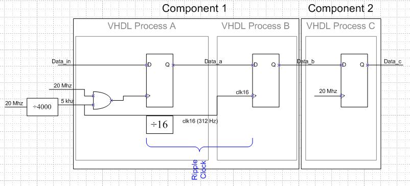
Link Copied
- Mark as New
- Bookmark
- Subscribe
- Mute
- Subscribe to RSS Feed
- Permalink
- Report Inappropriate Content
Is there some logic for clk16, or does it come directly from an input port.
When you do report_timing, make sure the -detail is set to full_path. Look at the Data Path tab and make sure the clock paths go all the way back to the input port. If so, it's all being accounted for. Are you looking in the Fast Corner timing model? The fitter is quite good at adding routing delays to meet hold timing(assuming Assignments -> Settings -> Fitter -> Optimize Hold is set to All Paths and Optimize Multicorner is checked). How do you know you have a failure?- Mark as New
- Bookmark
- Subscribe
- Mute
- Subscribe to RSS Feed
- Permalink
- Report Inappropriate Content
Clock 16 is divided down based off the 5khz which is based off the 20Mhz. The clk16 is created by a counter that counts up to 16 and creates a pulse that is one 5khz pulse wide.
How do I know I have a failure? Well I don't. We have some data glitches with this signal once in a while. I am learning ripple clock based designs have some downsides and clock enables should instead be used. I guess I'm still having trouble understanding or clearly seeing the delay between 20Mhz and clk16, which is my concern. But based on your suggestion, I do see the Data Path showing the end data going all the way back to the input clock and the delay is not very much. Maybe I just needed some convincing. I should mention, that this design previously had a mistaken set_false_path constraint which seperated the 20Mhz and clk16: set_false_path -from [get_registers {component_1|clk_16}] -to [get_clocks {20_Mhz}] Would this have changed the actual fitter or place and route? That constraint has since been deleted and my analysis above is a new place and route with the false_path statement deleted. I'll throw in my generated clock statements (simplified) just for additional checking: create_generated_clock -name 5Khz -source [get_pins {pll|20_Mhz}] -divide_by 4000 [get_pins {5khz_generator|regout}] create_generated_clock -name clk_16 -source [get_pins {5khz_generator|regout}] -divide_by 1 [get_registers {Component_1|clk_16}] Rsync, your wiki tutorial has been invaluable to me. I hope you find time to add the additional sections - including the section planned on ripple clocks.- Mark as New
- Bookmark
- Subscribe
- Mute
- Subscribe to RSS Feed
- Permalink
- Report Inappropriate Content
You see it on the Data Arrival Path too? If so, it should be fine. Feel free to write the report_timing of one path to a .txt file and attach it.
The only major trick with ripple clocks is to note that clocks do not propogate through registers, and so if the output of a register ever feeds the .clk pin of another register, the user must put a generated clock assignment on that original register. If you don't do this, you won't get any analysis on the downstream logic and the ripple clock should show up as an unconstrained clock(Report Unconstrained Paths). Since you're seeing the analysis, it should be correct. The major points if you really want a full analysis: - Is the setup relationship correct? - Is the hold relationship correct? - With -detail full_path, do the launch and latch clocks track back to the FPGA input ports? That's really the only things Quartus is figuring out from your .sdc, and what to look at to determine if the analysis is correct. Everything else is just delays from the place-and-route and not your .sdc. Thanks on the wiki user guide. I keep mean to go back to it, although other stuff keeps getting in the way. (There's a source-synchronous timinig user guide, a fitter and seed sweep guide, and am currently working on logiclock and design partition guide. Also trying to learn QSYS better...) Most likely when I do go back I'll trim down what I plan to add, although a few things could be done pretty quickly.- Mark as New
- Bookmark
- Subscribe
- Mute
- Subscribe to RSS Feed
- Permalink
- Report Inappropriate Content
Sorry for the delay. Thanks for the clock suggestion. I found that the data arrival path did not have an originating clock. There was also a warning in the console indicating this:
Info: The source clock for this clock assignment cannot be reached. Clock: clk_16 might not have valid arrival time. I believe this was because my generated_clock definitions were incorrect. I tried creating a series of two generated clocks: 5khz and clk_16 However, I realized this is incorrect because the generation of this clk_16 is really latched by the 20 Mhz clock edge with a 5khz clock enable (see my original picture). Therefore I think I only need one create_generated_clock cmd which generates the clk_16 from the 20Mhz. The 5khz is basically irrelavent. (Is this when multicycles can be used if needed?) So my only generated_clock is: create_generated_clock -name clk_16 -source [get_pins {pll|clk[4]}] -divide_by 4000 [get_registers {component_A|i_component_A|clk_16}] This removes the warning and shows the Data Required Path from the data all the way back through the pll to the input clock pin. This now makes sense. I attatched the timing result of the slowest path. Note I did rename everything so please ignore the names if they don't look quite right. Thanks again.- Mark as New
- Bookmark
- Subscribe
- Mute
- Subscribe to RSS Feed
- Permalink
- Report Inappropriate Content
Sounds like you've got it right. It can be confusing. I've had numerous times where I've banged my head on the desk trying to get a generated clock to work and it doesn't. Annoyingly, it generally goes back to me thinking the RTL works one way when it really is slightly different. I then make sure no one is looking, apologize to TimeQuest for the things I said, and move on. : )
- Mark as New
- Bookmark
- Subscribe
- Mute
- Subscribe to RSS Feed
- Permalink
- Report Inappropriate Content
Turns out the setup timing was ok, but the hold timing was not met due to the ripple clock. Quartus is NOT configured to have the fitter optimize internal registers (All Paths) and therefore wont automatically add delays to fix the hold timing. Instead the better solution is to simply change the design to a clock enable (now that I understand the timing problem clearly). I think it should have been enabled from the beginning, but don't want to change it at this point.
Just for my information, any additional options for having quartus optimize or add delays only to this path? I believe I can also define this clock as a global in the assignment editor which may or may not help.- Mark as New
- Bookmark
- Subscribe
- Mute
- Subscribe to RSS Feed
- Permalink
- Report Inappropriate Content
You mean is there a way to specify where it does and does not add delays? Not that I know of. From one standpoint, you always want it to add delays to meet timing, since you're design won't work if it doesn't. But it's nice to be able to disable, as adding delays can mask something that might be a mistake(missing multicycle hold) or designed better. The Estimated Delays Added report in the .fit.rpt is another way to see if the router is adding delays where it shouldn't. (Note that on a design with one clock on a Global, this estimated delay added will not be 0).
- Subscribe to RSS Feed
- Mark Topic as New
- Mark Topic as Read
- Float this Topic for Current User
- Bookmark
- Subscribe
- Printer Friendly Page