- Mark as New
- Bookmark
- Subscribe
- Mute
- Subscribe to RSS Feed
- Permalink
- Report Inappropriate Content
Hallo everybody,
I am trying out the "Nios II On-die Temperature Sensor Design Example" on the BeMicro Max 10 from Arrow.
The problem is that the temperature values displayed are wrong or at least unrealistic. I did everything according to instructions and played the .sof file, which is in the master_image folder, into the fpga. At room temperature a temperature of -19°C is displayed via the nios-terminal. I then according to the instructions created the project. Most important change I made was to set the voltage reference instead of external to internal and also to measure other inputs like the photoresistor on Ch. 4 according to the instructions from Arrow but no success.
I only see a constant value that does not change. I also searched the forum and came across this post which describes a similar problem to mine: https://community.intel.com/t5/Programmable-Devices/MAX10-ADC-problem/td-p/682051 How can I set the IP settings to continuous? As you can guess I am a beginner and would appreciate some tips. All important information about my setup.
Win10
Board
BeMicro Max 10 https://www.arrow.de/products/bemicromax10/arrow-development-tools
IDE
Quartus II Web Edition 14.1
Code
https://fpgacloud.intel.com/devstore/platform/14.1.0/Standard/nios-ii-on-die-temperature-sensor-design-example-bemicro/
I attach a screenshot of my created qsys file. By the way the buttons are fully functional and the LEDs goes on too. The C code is the same as in the example under the folder Software\ondie_temp.c.
Link Copied
- Mark as New
- Bookmark
- Subscribe
- Mute
- Subscribe to RSS Feed
- Permalink
- Report Inappropriate Content
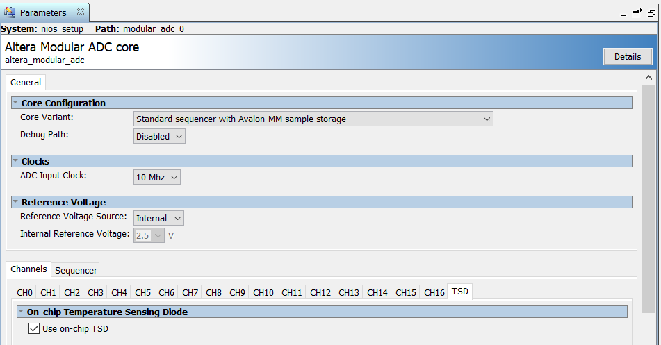
Can you show your parameter settings for the core? The TSD is on the first ADC in dual ADC devices.
You might also want to check this training that goes into the options for configuring the ADC:
https://www.intel.com/content/www/us/en/programmable/support/training/course/omaxadc102.html
- Mark as New
- Bookmark
- Subscribe
- Mute
- Subscribe to RSS Feed
- Permalink
- Report Inappropriate Content
Thank you for dealing with my problem!
I have only now realized that my FPGA from Arrow has the following identifier "10M08DAF484C8G" and the example I am using is for the "10M08DAF484I7N". The FPGA "10M08DAF484I7N" has two ADCs but mine "10M08DAF484C8G" has only one. This should not be the error, but here are the settings for the core on the two screenshots. I hope the example is valid anyway, otherwise maybe that would be the error already?
I created a repository for the code maybe it helps. If there are any problems in this regard, let me know.
https://github.com/GurkenIvanse/bemicromax10ADC
I will take the class.
- Mark as New
- Bookmark
- Subscribe
- Mute
- Subscribe to RSS Feed
- Permalink
- Report Inappropriate Content
so i have done my research and have now tried to implement the ADC without Nios. To do this I followed the youtube video. https://www.youtube.com/watch?v=0oO1RFa-4Xk&list=PLJCQGKgvE0JDbpdW0Apr3fN9lX-VkR3Qz
I have the same chip as in the video the "10M08DAF484C8GES" and I tried to create the ADC design in Qsys according to the video.
Thereby I noticed, he used for the CLK the PIN_M9, where I do not understand the sense, should it not be PIN_N14, which is the input for the systemclock? If you use PIN_N14 instead of PIN_M9 then you get the following error message "Error (170084): Can't route signal "ADC:inst|ADC_pll:pll|ADC_pll_altpll_5q22:sd1|wire_pll7_clk[0]" to atom "ADC: inst|ADC_adc:adc|altera_modular_adc_control:control_internal|fiftyfivenm_adcblock_top_wrapper:adc_inst|fiftyfivenm_adcblock_primitive_wrapper:adcblock_instance|primitive_instance"
If PIN_M9 is used, which should be the input of PLL_1, Quartus compiles the programm. But the ADC Toolkit in Qsys does not start and I get an error message "ADC Toolkit: No associated hardware detected".
This error has already been posted in the forum, again related to the ADC, but with no satisfying answer. https://community.intel.com/t5/Intel-Quartus-Prime-Software/ADC-Toolkit-No-associated-hardware-detected/td-p/1251003
The error must be somewhere when creating the Qsys file or when connecting the pins. I will keep trying, if anyone has any idea or so please write :D. Thank you!
- Mark as New
- Bookmark
- Subscribe
- Mute
- Subscribe to RSS Feed
- Permalink
- Report Inappropriate Content
Hi
you can also refer to Table 35 in https://www.intel.com/content/dam/www/programmable/us/en/pdfs/literature/hb/max-10/ug_m10_adc.pdf for Command Register setting of Max 10 ADC.
thanks.
Eng Wei
- Mark as New
- Bookmark
- Subscribe
- Mute
- Subscribe to RSS Feed
- Permalink
- Report Inappropriate Content
I have not read the document completely yet. Thank you for the advice already! I will go through the complete content and give feedback again.
- Subscribe to RSS Feed
- Mark Topic as New
- Mark Topic as Read
- Float this Topic for Current User
- Bookmark
- Subscribe
- Printer Friendly Page