- Mark as New
- Bookmark
- Subscribe
- Mute
- Subscribe to RSS Feed
- Permalink
- Report Inappropriate Content
Hello!
I've implemented a design with the altera PLL using the clock switchover, specifically auto switch with manual override. I have logic on my system base clock that determines if an incoming shared clock is bad (according to the PLL) and initiates a switch accordingly.
This logic all works well. However when I try to create my sdc file using the timing analyzer the "derive_pll_clocks" command fails because it cannot determine which clock to use.
Because of this I have manually created the create_generated_clocks for each of my clock paths in the PLL and have isolated them in clock groups.
For output_delay and input_delay commands, do I have to set them for each pin, based on each generated clock path? Is there a smarter way to do this? Why does derive pll clocks not work with clock switchover?
Attached my SDC file for clarity.
Link Copied
- Mark as New
- Bookmark
- Subscribe
- Mute
- Subscribe to RSS Feed
- Permalink
- Report Inappropriate Content
First of all, set_input_delay and set_output_delay should be referencing virtual clocks, the clocks that drive your connected devices (I call them upstream for input devices and downstream for devices fed by the FPGA). I don't see virtual clocks in your .sdc unless those are supposed to be your "clk_in" and "clk_out", in which case they should not have targets in the constraints.
And when you say "clock switchover", are you saying you are using a clock control block to switch what clock is going into the PLL? Maybe a little diagram or better explanation of your clock network would be helpful.
- Mark as New
- Bookmark
- Subscribe
- Mute
- Subscribe to RSS Feed
- Permalink
- Report Inappropriate Content
Thanks for your comments and reply!
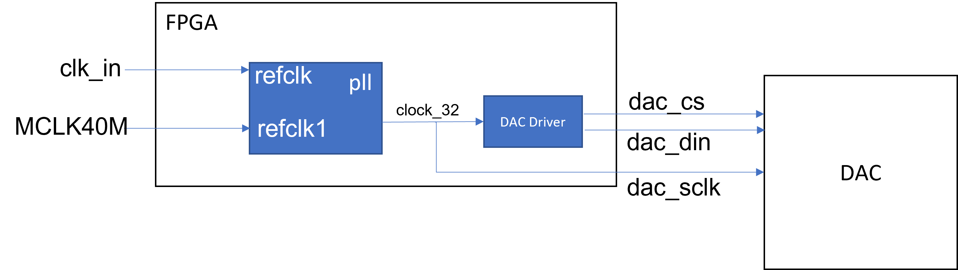
I've attached a picture that I hope will clarify what I'm trying to accomplish. I've attached a simplified SDC of how I believe I should be constraining the design. Since the clock driving the off-board dac originates from the FPGA I figured I should use a generated clock and not a virtual clock.
For clock switchover I have implemented the cyclone V PLL (http://www.altera.com/literature/ug/altera_pll.pdf) with the Automatic
Switchover with Manual Override. I have two incoming clocks and if "clk_in" is present and stable (determined by the clkbad port from the PLL) I want the device to switch to that clock, from the clock MCLK40M.
Both clocks are connected to clock pins on the FPGA so I am unclear as to why I would need to use the clock control block before wiring in the PLL. If this is the correct practice I'll happily comply.
- Mark as New
- Bookmark
- Subscribe
- Mute
- Subscribe to RSS Feed
- Permalink
- Report Inappropriate Content
Sorry, I forgot that the switchover feature can be part of the PLL itself instead of requiring the clock control block in front of it. I'm surprised derive_pll_clocks doesn't work with this. What does the "Report clocks" command in the timing analyzer show when you use derive_pll_clocks?
You have a typo in your first set_output_delay (double underscore). And what clock is dac_ld_sclk_int in the 4th one?
You're also missing -max and -min for your set_output_delay constraints. But you say max and min are the same at 5 V (?). Not sure if these are all typos.
- Mark as New
- Bookmark
- Subscribe
- Mute
- Subscribe to RSS Feed
- Permalink
- Report Inappropriate Content
I was also surprised. I believe the issue is that it is looking for a master clock to derive the generated clock. I don't really understand why it won't make the timing paths for both as they are mutually exclusive.
Specifically the timing analyzer throws "The base clock assignment for generated clock pll_inst|pll_inst|altera_pll_i|cyclonev_pll|fpll_0|fpll|vcoph[0] cannot be derived"
When I run report clocks it shows the issue:
"The master clock for this clock assignment could not be derived. Clock: pll_inst|asec_pll_inst|altera_pll_i|cyclonev_pll|fpll_0|fpll|vcoph[0] was not created."
"Clock: MCLK40M found as a potential master clock candidate"
"Clock: clk_in found as a potential master clock candidate"
Digging into the PLL it seems that the derive PLL clocks command usually derives the base clock at the VCO and then generates the rest of the clocks off of this generated clock.
Sorry I was trying to match my diagram quickly. I have quite a few more signals in my full design so I was just trying to simplify it. Those typos don't really exist in the true SDC file which is much longer. (dac_ld_sclk_int is the real signal).
I believe omitting -max and -min is the same as indicating -both, since the setup and hold times are same value per my device data sheet (at 5V, sorry again the comment was to remind future-me of why they're the same).
- Mark as New
- Bookmark
- Subscribe
- Mute
- Subscribe to RSS Feed
- Permalink
- Report Inappropriate Content
Perhaps you need to use the -create_base_clocks option when you do this.
The "5V" was confusing because we're talking about time, not voltage. In general, you do not want to have the same value for both -max and -min with set_output_delay. -max is for meeting setup timing and -min is for meeting hold timing.
- Mark as New
- Bookmark
- Subscribe
- Mute
- Subscribe to RSS Feed
- Permalink
- Report Inappropriate Content
I did have that option checked. I even tried deleting the base clocks, rerunning, but still got the same issues. At this point I'm closing timing and everything is checking out on my peripherals by manually defining the clocks. I just thought (hoped) that there was a cleaner /easier way to accomplish it.
I appreciate you taking the time and the advice! Typically I agree regarding the delay, but in this case the data sheet listed the same value for both setup and hold. ¯\_(ツ)_/¯
Thanks for responding to me. Cheers!
- Mark as New
- Bookmark
- Subscribe
- Mute
- Subscribe to RSS Feed
- Permalink
- Report Inappropriate Content
Hi,
Sorry for the late response. Does the above reply help?
- Mark as New
- Bookmark
- Subscribe
- Mute
- Subscribe to RSS Feed
- Permalink
- Report Inappropriate Content
Hi,
We did not receive any response to the previous question/reply/answer provided, thus I will put this case to close pending. Please post a response in the next 15 days to allow me to continue to support you. After 15 days, this thread will be transitioned to community support. The community users will be able to help you with your follow-up questions.
Regards,
Nurina
- Mark as New
- Bookmark
- Subscribe
- Mute
- Subscribe to RSS Feed
- Permalink
- Report Inappropriate Content
Hello,
The above answers does "solve" the problem but I'd like to know if this is the proper way to constrain the design per Intel? I'd also like feedback from intel as to why "derive_pll_clocks" does not work for the PLL using clock switchover?
Tyler
- Subscribe to RSS Feed
- Mark Topic as New
- Mark Topic as Read
- Float this Topic for Current User
- Bookmark
- Subscribe
- Printer Friendly Page