- Mark as New
- Bookmark
- Subscribe
- Mute
- Subscribe to RSS Feed
- Permalink
- Report Inappropriate Content
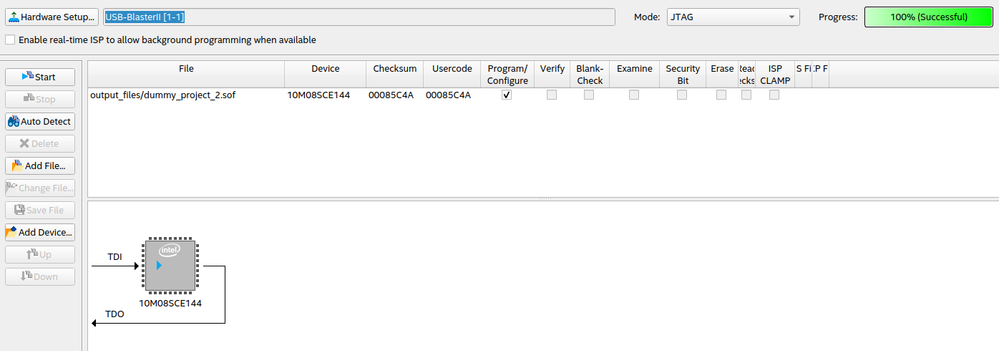
I have a custom made board with a MAX10 FPGA. I had this board working for about one year without issues. Last week I replaced the 10M04SCE144C8G old FPGA with a brand new 10M08SCE144I7G. I changed the device selection in Quartus to match the new FPGA. Now I can program it using Quartus Lite (I get a "success" message) but the outputs of the FPGA are just fixed at 3.3 V (logic 1). Is there any "one time configuration" that has to be done when the device is new?
Link Copied
- Mark as New
- Bookmark
- Subscribe
- Mute
- Subscribe to RSS Feed
- Permalink
- Report Inappropriate Content
Did you recompile the Quartus project for the new device?
- Mark as New
- Bookmark
- Subscribe
- Mute
- Subscribe to RSS Feed
- Permalink
- Report Inappropriate Content
Yes, I did recompile the project after selecting the new device. I am suspecting of a fake device. I bought it in a random place in Hong Kong because of the shortage in all reliable distributors. However aesthetically it looks very nice and also the "autodetect" feature on the JTAG programmer does detect the correct device. What I cannot do is to program the flash memory.
- Mark as New
- Bookmark
- Subscribe
- Mute
- Subscribe to RSS Feed
- Permalink
- Report Inappropriate Content
What do you mean by programming flash? Writing .pof or some manual things? Can you get output when programming with .sof?
- Mark as New
- Bookmark
- Subscribe
- Mute
- Subscribe to RSS Feed
- Permalink
- Report Inappropriate Content
Yes, so if I select the `.sof` file I can click on the "program" button and after it does something Quartus says "success" with the green light. In this case, however, the FPGA does nothing, it is as if nothing was done. If I try also with the `.pof` file it says "failed" and I get `Error (209031): Device chain in Chain Description File does not match physical device chain -- expected 2 device(s) but found 1 device(s).`.
- Mark as New
- Bookmark
- Subscribe
- Mute
- Subscribe to RSS Feed
- Permalink
- Report Inappropriate Content
It seems that the reason of failing .pof is you are forgetting the add the flash device. But still you must get output when you programmed .sof succesfully. Did you try simple LED drive or etc., and make sure you correctly mapped your pins. After a new device select the pin mappings will be erased.
- Mark as New
- Bookmark
- Subscribe
- Mute
- Subscribe to RSS Feed
- Permalink
- Report Inappropriate Content
... I bought it in a random place in Hong Kong because of the shortage in all reliable distributors ...
You answered your own question as to why your board is not working.
- Mark as New
- Bookmark
- Subscribe
- Mute
- Subscribe to RSS Feed
- Permalink
- Report Inappropriate Content
I am trying with a very simple dummy project. This is my code:
```verilog
module dummy_project_2(
input CLOCK1,
input CLOCK2,
input CLOCK3,
input CLOCK4,
output OUT1,
output OUT2,
output test_pin
);
assign OUT1 = CLOCK1;
assign OUT2 = 1'b0;
assign test_pin = 1'b0;
endmodule
```
I have a fast oscilloscope connected to `OUT1` and `OUT2`, and I am using `test_pin` to test random pins. I have set the pins like this:
- Mark as New
- Bookmark
- Subscribe
- Mute
- Subscribe to RSS Feed
- Permalink
- Report Inappropriate Content
Hello,
Are you able to snapshot the top marking print? I can check if the device coming from intel or not.
regards,
Farabi
- Mark as New
- Bookmark
- Subscribe
- Mute
- Subscribe to RSS Feed
- Permalink
- Report Inappropriate Content
- Mark as New
- Bookmark
- Subscribe
- Mute
- Subscribe to RSS Feed
- Permalink
- Report Inappropriate Content
Hello,
I have confirmed with QRE by verifying the datecode and lot number.
This device is genuine device.
regards,
Farabi
- Mark as New
- Bookmark
- Subscribe
- Mute
- Subscribe to RSS Feed
- Permalink
- Report Inappropriate Content
Do you have the exposed pad on the bottom of the chip connected to ground?
- Mark as New
- Bookmark
- Subscribe
- Mute
- Subscribe to RSS Feed
- Permalink
- Report Inappropriate Content
Hi,
I am waiting for QRE to check the top marking. will update you later.
regards,
Farabi
- Mark as New
- Bookmark
- Subscribe
- Mute
- Subscribe to RSS Feed
- Permalink
- Report Inappropriate Content
Hello,
I’m glad that your question has been addressed, I now transition this thread to community support.
If you have a new question, feel free to open a new thread to get the support from Intel experts.
Otherwise, the community users will continue to help you on this thread. Thank you.
regards,
Farabi
- Subscribe to RSS Feed
- Mark Topic as New
- Mark Topic as Read
- Float this Topic for Current User
- Bookmark
- Subscribe
- Printer Friendly Page


