- Mark as New
- Bookmark
- Subscribe
- Mute
- Subscribe to RSS Feed
- Permalink
- Report Inappropriate Content
Hello,
This is the code for the clock that displays minutes/seconds, and attaches the project folder.
The written code works fine, but the first digit of the second position becomes '4' upon reset.
That is, 04,05,06,07,08,09 -> 10,11,12,13,14,15,16,17,18,19 -> 20,21,22,23, was expected.
The problem works as 14,15,16,17,18,19 -> 24,25,26,27,28,29 -> 34,35....
I have a question.
There is nothing wrong with the code in the Verilog HDL editor,
Is there a place where I write code that can affect the behavior in other areas that are not visible to me?
For example,
Is there a place to write scripts?
Is there a place to write the header file?
Is it possible to insert hidden characters in the editor?
I wonder if code can be injected during compilation, etc.?
If possible, what can I do to prevent this problem?
Because, I feel like someone is tampering with my PC's Quartus from a remote location.
thank you.
Quartus 20.1.1 (image attached)
FPGA: M10, 10M08SCU169, 50MHz Clock
BOARD: QMTECH_MAX10_10M08SCU169
Coding Purpose: For Minute/Second Clock
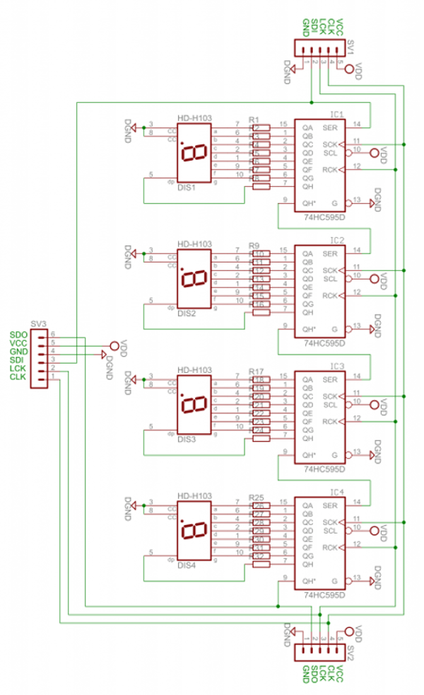
Peripheral: 74HC595 Built-in 7-segment LED (with schematic image attached)
Link Copied
- Mark as New
- Bookmark
- Subscribe
- Mute
- Subscribe to RSS Feed
- Permalink
- Report Inappropriate Content
The designed 4-digit 7-segments were coded for 24 hours and 60 minutes.
Currently attached coding is counted up in 1 second cycle for testing.
- Mark as New
- Bookmark
- Subscribe
- Mute
- Subscribe to RSS Feed
- Permalink
- Report Inappropriate Content
Hi,
What do you mean by " first digit of the second position becomes '4' upon reset".
Thanks,
Ean
- Mark as New
- Bookmark
- Subscribe
- Mute
- Subscribe to RSS Feed
- Permalink
- Report Inappropriate Content
Hi,
Do you have any update on your problem?
Thanks,
Ean
- Mark as New
- Bookmark
- Subscribe
- Mute
- Subscribe to RSS Feed
- Permalink
- Report Inappropriate Content
Hi,
I still don't understand.
I wrote a 4-bit counter asynchronously, and it was written to reset all 4 bits at the same time, but I don't understand whether bit0, 1, 3 become "0" and bit2 becomes "1".
After I uploaded a question to https://community.intel.com/
The programming seems to be complete, but the board does nothing.
Can you understand why this MAX10_10M02SCU169 board is not working?
I haven't made any progress since then. ^^
Because my MAX10_10M02SCU169 board is broken.......
I'm sorry I couldn't give you good news.
Regards.
- Mark as New
- Bookmark
- Subscribe
- Mute
- Subscribe to RSS Feed
- Permalink
- Report Inappropriate Content
Hi,
You may use ModelSim to create testbench and observe the output signals. I have tried to create a testbench for it but there was no result. This is because the output was not the 7-segment display. I have tried to run another similar example from https://www.fpga4student.com/2017/09/seven-segment-led-display-controller-basys3-fpga.html , the output was the 7-segment display so I'm able to observe the output signals.
Thanks,
Ean
- Mark as New
- Bookmark
- Subscribe
- Mute
- Subscribe to RSS Feed
- Permalink
- Report Inappropriate Content
Hi,
We do not receive any response from you to the previous question that have provided. This thread will be transitioned to community support. If you have a new question, feel free to open a new thread to get the support from Intel experts. Otherwise, the community users will continue to help you on this thread. Thank you.
Regards,
Ean
- Subscribe to RSS Feed
- Mark Topic as New
- Mark Topic as Read
- Float this Topic for Current User
- Bookmark
- Subscribe
- Printer Friendly Page