- Mark as New
- Bookmark
- Subscribe
- Mute
- Subscribe to RSS Feed
- Permalink
- Report Inappropriate Content
This post is an offshoot of an earlier post entitled
"Are divided clocks synchronous with the source clock?"
I have a cpld design with 5 different clock domains. There is a slow master clock (1.432MHz, T = 542ns), and 4 (integer) divided clocks generated from the master by separate synchronous counters. The positive edge of each divided clock should then be one Tco behind a positive edge of the source clock, and data in the divided clock domains should be another Tco delayed behind the positive edge of the divided clock. I assumed this was a fixed phase relationship that meant all these domains were synchronous. But Quartus doesn't agree.
I had warnings on every domain crossing: Critical Warning (308060): (High) Rule D101: Data bits are not synchronized when transferred between asynchronous clock domains
There were also hold time violations on signals transferred to the master clock domain. I got rid of these by clocking data out of the master clock domain on the negative edge of the master clock and into the slower domains on the positive edges of the divided clocks. That way there is always at least 270ns of setup and hold time in the divided clock domains.
The result of the above was a new warning: Warning (308022): (Medium) Rule C106: Clock signal source should not drive registers triggered by different clock edges. Is this something I need to be concerned about?
I do have generated clock constraints in my SDC file stating that the divided clocks are integer divisions of the master, but still have "Data bits not synchronized" warnings. Do I need to add synchronizers to every bit? I have synch'ed data ready flags and latched data when they are asserted, but Quartus is still unhappy.
Any help is greatly appreciated
Link Copied
- Mark as New
- Bookmark
- Subscribe
- Mute
- Subscribe to RSS Feed
- Permalink
- Report Inappropriate Content
Can you show your .sdc and maybe a drawing of your clock network at this point? It's a little hard to visualize.
You're using such low clock speeds that it's surprising that you'd run into any timing issues, though I guess the hold timing issues may be more of a trampling of the next clock cycle by a previous one.
- Mark as New
- Bookmark
- Subscribe
- Mute
- Subscribe to RSS Feed
- Permalink
- Report Inappropriate Content
Hello,
Happy New Year and thanks for your help. I am attaching the sdc file and a pdf showing the clock tree structure. The clock definitions from the sdc are pasted below the dotted line
Jim
----------------------------------------------------------------------------------------------------------------------
#**************************************************************
# Create Clock
#**************************************************************
create_clock -name {clock_in_3p6864mhz} -period 271.000 -waveform { 0.000 135.000 } [get_ports {clock_in_3p6864mhz}]
create_clock -name {cpld_master_clock} -period 542.000 -waveform { 0.000 271.000 } [get_nets {cpld_master_clock}]
#**************************************************************
# Create Generated Clock
#**************************************************************
create_generated_clock -name {uart_rx_clock} -source [get_nets {cpld_master_clock}] -divide_by 2 -master_clock {cpld_master_clock} [get_registers {clock_divider:CDIV2|clk_out}]
create_generated_clock -name {uart_tx_clock} -source [get_nets {cpld_master_clock}] -divide_by 32 -master_clock {cpld_master_clock} [get_registers {clock_divider:CDIV3|clk_out}]
create_generated_clock -name {millisec_clock} -source [get_nets {cpld_master_clock}] -divide_by 1920 -master_clock {cpld_master_clock} [get_registers {clock_divider:CDIV4|clk_out}]
create_generated_clock -name {heartbeat_clock} -source [get_nets {cpld_master_clock}] -divide_by 3840 -master_clock {cpld_master_clock} [get_registers {clock_divider:CDIV5|clk_out}]
- Mark as New
- Bookmark
- Subscribe
- Mute
- Subscribe to RSS Feed
- Permalink
- Report Inappropriate Content
Your second create_clock should be a create_generated_clock since it's sourced from the input clock. And you should always try to use get_pins for your targets instead of get_nets. You can use the Name Finder through the Quartus Text Editor SDC GUI dialog boxes to find the correct targets.
- Mark as New
- Bookmark
- Subscribe
- Mute
- Subscribe to RSS Feed
- Permalink
- Report Inappropriate Content
Thanks for your reply. I am trying to implement your advice, but so far unsuccessfully.
I used the post-fit netlist viewer to try to figure out the correct names. Here are the constraints I created in the Timing Analyzer using the post-fit names:
create_generated_clock -name {cpld_master_clock} -source [get_ports {clock_in_3p6864mhz}] -divide_by 2 -master_clock {clock_in_3p6864mhz} [get_pins {CDIV1|clk_in_count[0]|regout}]
create_generated_clock -name {uart_rx_clock} -source [get_pins {cpld_master_clock|combout}] -divide_by 2 -master_clock {clock_divider:CDIV1|clk_out} [get_pins {CDIV2|clk_out|regout}]
create_generated_clock -name {uart_tx_clock} -source [get_pins {cpld_master_clock|combout}] -divide_by 16 -master_clock {clock_divider:CDIV1|clk_out} [get_pins {CDIV3|clk_out|regout}]
create_generated_clock -name {millisec_clock} -source [get_pins {cpld_master_clock|combout}] -divide_by 1920 -master_clock {clock_divider:CDIV1|clk_out} [get_pins {CDIV4|clk_out|regout}]
create_generated_clock -name {heartbeat_clock} -source [get_pins {cpld_master_clock|combout}] -divide_by 2 -master_clock {clock_divider:CDIV1|clk_out} [get_pins {CDIV5|clk_out|regout}]
The Quartus fitter rejected all but the first one. The error messages are below:
Info (332104): Reading SDC File: 'Mk1_Safety_Unit_CPLD.out.sdc'
Warning (332087): The master clock for this clock assignment could not be derived. Clock: uart_rx_clock was not created.
Warning (332034): Specified master clock: clock_divider:CDIV1|clk_out not found on or feeding the specified source node: cpld_master_clock|combout
Warning (332087): The master clock for this clock assignment could not be derived. Clock: uart_tx_clock was not created.
Warning (332034): Specified master clock: clock_divider:CDIV1|clk_out not found on or feeding the specified source node: cpld_master_clock|combout
Warning (332087): The master clock for this clock assignment could not be derived. Clock: millisec_clock was not created.
Warning (332034): Specified master clock: clock_divider:CDIV1|clk_out not found on or feeding the specified source node: cpld_master_clock|combout
Warning (332087): The master clock for this clock assignment could not be derived. Clock: heartbeat_clock was not created.
Warning (332034): Specified master clock: clock_divider:CDIV1|clk_out not found on or feeding the specified source node: cpld_master_clock|combout
Warning (332060): Node: clock_divider:CDIV1|clk_out was determined to be a clock but was found without an associated clock assignment.
Warning (332060): Node: clock_divider:CDIV3|clk_out was determined to be a clock but was found without an associated clock assignment.
Warning (332060): Node: clock_divider:CDIV2|clk_out was determined to be a clock but was found without an associated clock assignment.
Warning (332060): Node: clock_divider:CDIV5|clk_out was determined to be a clock but was found without an associated clock assignment.
Warning (332060): Node: clock_divider:CDIV4|clk_out was determined to be a clock but was found without an associated clock assignment.
I think I'm on the right track, but I don't yet have the names that the fitter wants to see for the -source_clock and/or -master_clock fields.
I am attaching a screenshot of the post-fit netlist viewer output showing the output of CDIV1 and the global buffer that follows it. The global buffer output feeds dividers CDIV2-5 but what should I use as the source pin in the constraints for CDIV2-5? Apparently cpld_master_clock|combout isn't right.
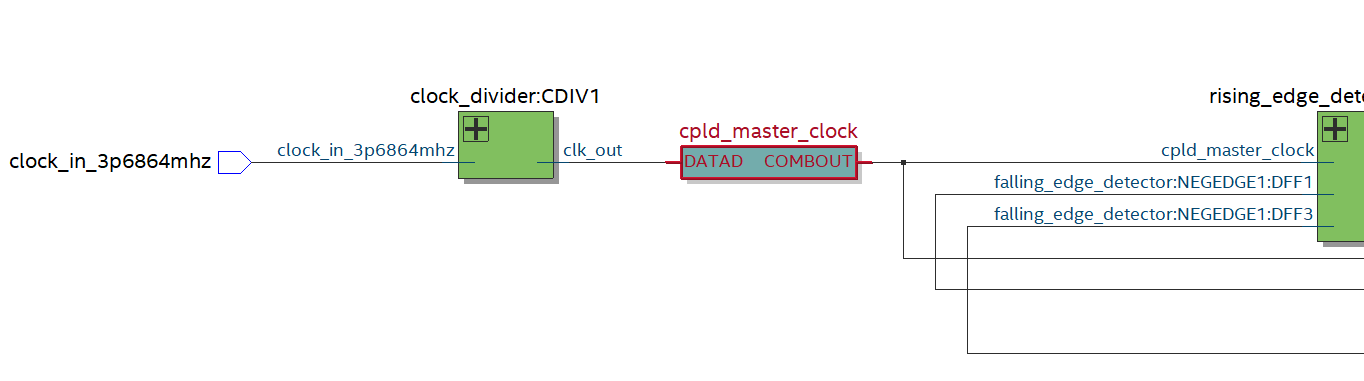
- Mark as New
- Bookmark
- Subscribe
- Mute
- Subscribe to RSS Feed
- Permalink
- Report Inappropriate Content
I made some progress. Saw an error in the target pin for the cpld_master_clock and corrected it. Also changed the source clock definition for each divider from -source [get_pins {cpld_master_clock|combout}] to -source [get_nets {cpld_master_clock}].
Why would get_pins{ } be better than get_nets{ }?
Quartus was happy with this and all the synchronization warnings disappeared.
The constraints are now:
#**************************************************************
# Create Clock
#**************************************************************
create_clock -name {clock_in_3p6864mhz} -period 271.000 -waveform { 0.000 135.000 } [get_ports {clock_in_3p6864mhz}]
#**************************************************************
# Create Generated Clock
#**************************************************************
create_generated_clock -name {cpld_master_clock} -source [get_ports {clock_in_3p6864mhz}] -divide_by 2 -master_clock {clock_in_3p6864mhz} [get_pins {CDIV1|clk_out|regout}]
create_generated_clock -name {uart_rx_clock} -source [get_nets {cpld_master_clock}] -divide_by 2 -master_clock {cpld_master_clock} [get_pins {CDIV2|clk_out|regout}]
create_generated_clock -name {uart_tx_clock} -source [get_nets {cpld_master_clock}] -divide_by 32 -master_clock {cpld_master_clock} [get_pins {CDIV3|clk_out|regout}]
create_generated_clock -name {millisec_clock} -source [get_nets {cpld_master_clock}] -divide_by 1920 -master_clock {cpld_master_clock} [get_pins {CDIV4|clk_out|regout}]
create_generated_clock -name {heartbeat_clock} -source [get_nets {cpld_master_clock}] -divide_by 2048 -master_clock {cpld_master_clock} [get_pins {CDIV5|clk_out|regout}]
- Mark as New
- Bookmark
- Subscribe
- Mute
- Subscribe to RSS Feed
- Permalink
- Report Inappropriate Content
First, you don't need the master_clock option. That's only needed if there are multiple clocks at the source for a generated clock.
Second, you can't use the netlist viewer to get the correct SDC targets. Use the Name Finder found in any of the GUI dialog boxes you can access from the Edit menu when you're editing a .sdc file in the Quartus Text Editor.
I recommend get_pins because it is always a physical node in the design and there's less chance the name may change.
Glad you cleared the errors.
- Mark as New
- Bookmark
- Subscribe
- Mute
- Subscribe to RSS Feed
- Permalink
- Report Inappropriate Content
Thanks for your reply.
The reason I used the netlist viewer was to confirm which names I should select from the name finder. The names on the Name Finder list are created by the tool, not the HDL, and it's not obvious to me what they actually are until I look at the circuit in he netlist viewer.
I am using the post-fit netlist. Is that not the actual implementation? It seems intuitive that the pin, net, and node names in that netlist would be the same as in the Name Finder. You are saying that's not the case. If so, where do the Name Finder lists come from? Is it the timing netlist, and will that be different from the post-fit netlist?
Thanks again
- Mark as New
- Bookmark
- Subscribe
- Mute
- Subscribe to RSS Feed
- Permalink
- Report Inappropriate Content
The Name Finder is based off the official SDC timing netlist for the design, which, while similar to the post-synthesis or post-fit netlists from Quartus, is what is required for correct targeting for timing analysis. Using the dialog boxes also guarantees correct formatting of the SDC constraints.
- Mark as New
- Bookmark
- Subscribe
- Mute
- Subscribe to RSS Feed
- Permalink
- Report Inappropriate Content
Ok, thanks.
I would like to get back to my original question on Timing closure now that my clock constraints are good and I have no more synchronization warnings.
A quick update: I have 1.8432MHz master clock which is divided by 4 synchronous counters to produce 4 generated clocks. to Quartus, the generated clocks are not synchronous with the master clock because the rising edges of each trail the rising edge of the master by one Tco. This Tco delay was (I think) the source of hold violations when signals from the generated clock domains were passed to the master clock domain. I eliminated these errors by clocking data from the generated clock domains into the master domain on the falling edge of the master clock. This made sense to me because there should be a minimum delay from the rising edge of any generated clock to the falling edge of the master clock of at least 270ns.
However I get a warning now about using both edges of the master clock. Do I have to worry about this? I only use the up edge of the master clock to generate divided clocks, and the negative edge of the master to sync data from the divided clock domains to the master clock domain.
Thanks
- Mark as New
- Bookmark
- Subscribe
- Mute
- Subscribe to RSS Feed
- Permalink
- Report Inappropriate Content
Hi Jim,
Any update from the previous reply? Probably share your .sdc file.
- Mark as New
- Bookmark
- Subscribe
- Mute
- Subscribe to RSS Feed
- Permalink
- Report Inappropriate Content
Hi Jim,
Any update?
- Mark as New
- Bookmark
- Subscribe
- Mute
- Subscribe to RSS Feed
- Permalink
- Report Inappropriate Content
Hello SyafieqS,
No updates on my end, I am still waiting for someone to answer the original question. I restated the question in my previous post
Jim
- Subscribe to RSS Feed
- Mark Topic as New
- Mark Topic as Read
- Float this Topic for Current User
- Bookmark
- Subscribe
- Printer Friendly Page