- Mark as New
- Bookmark
- Subscribe
- Mute
- Subscribe to RSS Feed
- Permalink
- Report Inappropriate Content
Hello,
I am working on a design with transceiver.
I would like to know what is rx_pma_iqtxrx_clkout signal ?
What are the usage scenario's of rx_pma_iqtxrx_clkout signal ?
Thanks & Regards,
Sachin Jadhav
Link Copied
- Mark as New
- Bookmark
- Subscribe
- Mute
- Subscribe to RSS Feed
- Permalink
- Report Inappropriate Content
- Mark as New
- Bookmark
- Subscribe
- Mute
- Subscribe to RSS Feed
- Permalink
- Report Inappropriate Content
Hello dlim,
Thank you for responding.
I am cascading output clock(rx_pma_clkout) of RX PMA to the reference clock of fPLL instance so as to generate transmit clock.
I have configured RX PMA CDR to use local on-board reference clock as source. Local reference clock frequency is 108Mhz.
Transceiver is configured with Data rate is set to 1.62G and Data width is 32bit in PCS direct mode.
I am manually controlling RX CDR.
Below is my observation.
1) When rx_set_locktodata, rx_set_locktoref is 2'b00, I see a very jittery clock on rx_pma_clkout.
2) When rx_set_locktodata, rx_set_locktoref is 2'b01, I see a very clean 50.625 Mhz clock
3) When rx_set_locktodata, rx_set_locktoref is 2'b1X, I see a very clean of 31.38Mhz (What is the source of this clock)
In my test setup as of now I don't have any high speed data reception on serdes.
Why CDR is outputing 31.38 Mhz when rx_set_locktodata, rx_set_locktoref is 2'b1X ?
I also don't see my fPLL instance getting locked, when I set CDR to rx_set_locktodata, rx_set_locktoref is 2'b01.
Do I need to calibrate PLL for getting locked whenever there is change in rx_set_locktodata and rx_set_locktoref combination ?
Thanks & Regards,
Sachin Jadhav
- Mark as New
- Bookmark
- Subscribe
- Mute
- Subscribe to RSS Feed
- Permalink
- Report Inappropriate Content
Hi Sachin Jadhav,
Pls see my reply below
- Did you check CDR lock status ?
- The best way to ensure CDR is working correctly is to check on "rx_is_lockedtodata" or "rx_is_lockedtoref" signal depend on which CDR lock mode you are using
- What's the lock status when you set it to either LTR mode or LTD mode
- Confirm CDR lock mode is setup correctly
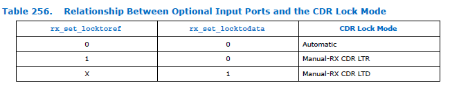
- Sorry, your explanation on CDR lock mode setting is unclear to me. Can you confirm are you setting it correctly as per below attached pic ?
- I presume you are getting 50.625MHz when you set it to lock to ref (LTR) mode and got 31.38MHz when set it to lock to data (LTD) mode. I suspect your on board incoming data is transferred at around 1Gbps instead of 1.62Gbps.
- fPLL should lock if rx_pma_clkout is stable and output correct frequency
Thanks.
Regards,
dlim
- Mark as New
- Bookmark
- Subscribe
- Mute
- Subscribe to RSS Feed
- Permalink
- Report Inappropriate Content
Hello Dlim,
During entire test scenario there is not data coming on rx lane of serdes. Basically no external wire is connected to entire serdes port.
Below is my observation.
1) When CDR is set to LTR mode, rx_is_lockedtoref is getting set and I am seeing 50.625 Mhz clock from rx_pma_clkout.
2) When CDR is set to LTD mode, rx_is_lockedtodata is getting set and I am seeing 31.38 Mhz clock from rx_pma_clkout.
As my rx lane of serdes is not receiving any data why does CDR locks when set to LTD mode and outputs 31.38 Mhz clock ?
For this experiment I have used Arria 10 transceiver toolkit and modified IP instances for required data rate.
I have also edited top level so as to observe clock and control signals on sma connector for debugging.
Thanks & Regards,
Sachin Jadhav
- Mark as New
- Bookmark
- Subscribe
- Mute
- Subscribe to RSS Feed
- Permalink
- Report Inappropriate Content
- Mark as New
- Bookmark
- Subscribe
- Mute
- Subscribe to RSS Feed
- Permalink
- Report Inappropriate Content
Hello Dlim,
I have routed rx_is_lockedtodata signal to sma connector(J7) on board. Which is connected to oscilloscope.
I see toggling behavior of rx_is_lockedtodata if CDR is set to AUTO(rx_set_lockedtoref, rx_set_lockedtodata -> 2'b00).
But if I set CDR to MANUAL mode (rx_set_lockedtoref, rx_set_lockedtodata -> 2'b01/2'b11) I see rx_is_lockedtodata is high and stable.
In this case I also see rx_pma_clkout giving 31.38Mhz.
Thanks & Regards,
Sachin Jadhav
- Mark as New
- Bookmark
- Subscribe
- Mute
- Subscribe to RSS Feed
- Permalink
- Report Inappropriate Content
- Mark as New
- Bookmark
- Subscribe
- Mute
- Subscribe to RSS Feed
- Permalink
- Report Inappropriate Content
Hello Dlim,
I have gone through "ug_arria10_xcvr_phy.pdf"
The reset sequence suggested by you is important from reception/transmission of data.
My test scenario is about clock generation, that too specifically about CDR block.
I want to understand why CDR block generates 31.38 Mhz clock if no input is present on Rx lane and rx_set_lockedtodata is high ?
This is important because in my design I will be using RX pma clock as a reference clock to a fPLL instance.
For better understanding if you could share below things it would be helpful.
1) Block diagram listing out analog block and digital blocks.
2) Various reset signals controlling analog block and digital block.
3) AC-DC Characteristics of each analog block.
4) Input-Output specification of each digital block.
Thanks & Regards,
Sachin Jadhav
- Mark as New
- Bookmark
- Subscribe
- Mute
- Subscribe to RSS Feed
- Permalink
- Report Inappropriate Content
- Mark as New
- Bookmark
- Subscribe
- Mute
- Subscribe to RSS Feed
- Permalink
- Report Inappropriate Content
Hello Dlim,
Thank you for the confirmation.
I have further question.
I have connected rx_pma_iqrxtx_clkout signal to the reference input clock pin of a fPLL instance.
I don't see fPLL getting locked ? Do you have any suggestion why fPLL is not getting locked ?
How do I debug the reason for fPLL not getting locked.
If I simply replace fPLL reference input clock with an on-board oscillator input then fPLL gets locked.
Thanks & Regards,
Sachin Jadhav
- Mark as New
- Bookmark
- Subscribe
- Mute
- Subscribe to RSS Feed
- Permalink
- Report Inappropriate Content
- Mark as New
- Bookmark
- Subscribe
- Mute
- Subscribe to RSS Feed
- Permalink
- Report Inappropriate Content
Hello Dlim,
As of now I am manually configuring CDR in LTR mode and expect a stable rx_pma_iqrxtx_clkout.
What is the correct way of constraining rx_pma_iqrxtx_clkout signal for low jitter.
I will also try to add a clock control block before fPLL.
Is there any more surgical method to find the root cause ?
Thanks & Regards,
Sachin Jadhav
- Mark as New
- Bookmark
- Subscribe
- Mute
- Subscribe to RSS Feed
- Permalink
- Report Inappropriate Content
- Mark as New
- Bookmark
- Subscribe
- Mute
- Subscribe to RSS Feed
- Permalink
- Report Inappropriate Content
Hello Dlim,
I tried the clock control suggestion, but it didn't worked.
I have also filed a new Forum case for fPLL lock issue.
Your help is appreciated.
Thanks & Regards,
Sachin Jadhav
- Subscribe to RSS Feed
- Mark Topic as New
- Mark Topic as Read
- Float this Topic for Current User
- Bookmark
- Subscribe
- Printer Friendly Page