- Mark as New
- Bookmark
- Subscribe
- Mute
- Subscribe to RSS Feed
- Permalink
- Report Inappropriate Content
currently i am using Cyclone II family libraries to implement a bbs prng
i have insert a coding that i copy from internet, but i quite confuse on understanding the coding the coding i'm using to make modification: library IEEE; use IEEE.STD_LOGIC_1164.ALL; use IEEE.STD_LOGIC_ARITH.ALL; use IEEE.STD_LOGIC_UNSIGNED.ALL; entity bbs is Port ( p : in integer; q : in integer; s : in integer; b : out STD_LOGIC_VECTOR(7 downto 0) ); end bbs; architecture Behavioral of bbs is begin process(p,q,s) variable x0,x1,s1,x_0:integer; constant p:integer:=11; constant q:integer:=19; constant n:integer:=551; variable b1:integer ; variable b2:std_logic; variable r:std_logic_vector(7 downto 0); begin s1:=s*s; x0:=s1 mod 1024; for i in 0 to 7 loop x_0:=x0*x0; x1:=x_0 mod 1024; b1:=x1 mod 2; if b1=1 then b2:='1'; else b2:='0'; end if; r(6):=r(7); r(5):=r(6); r(4):=r(5); r(3):=r(4); r(2):=r(3); r(1):=r(2); r(0):=r(1); r(7):=b2;--so it will be serially transmitted but parallelly observed x0:=x1; b<=r; end loop; end process; end Behavioral; please if there is someone can help me on explaining the coding?Link Copied
4 Replies
- Mark as New
- Bookmark
- Subscribe
- Mute
- Subscribe to RSS Feed
- Permalink
- Report Inappropriate Content
Hi,
Try to simulate and understand the operation, Also refer the following points, In given code input ‘s’ has significance. Check operation of Mod operator. When s=0 leads to b1=0 so b2 =0 hence r<=b<=00000000, When s=1 leads to b1=1 so b2 =1 hence r<=b<=11111111. --- Quote Start --- r(7):=b2;--so it will be serially transmitted but parallelly observed --- Quote End --- In for loop, eventually output vector b (b<=r) is updated, Check screen shot. Let me know if this has helped resolve the issue you are facing or if you need any further assistance. Best Regards Vikas Jathar Intel Customer Support – Engineering (Under Contract to Intel)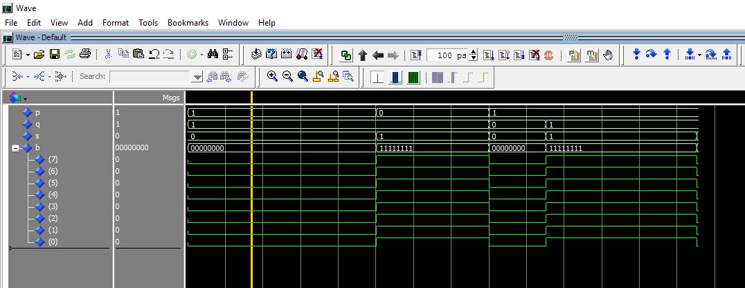
- Mark as New
- Bookmark
- Subscribe
- Mute
- Subscribe to RSS Feed
- Permalink
- Report Inappropriate Content
hi jatharvk, thanks for your information
i refer to your sreenshot, how you assign the input p, q, and s as 1 bit? because when i assign p, q and s node into the quartus II waveform window, it show 3 of these nodes are in 32 bits and since i need my output should be in random value, the output result is only showed as "00000000" and "11111111" how can i modify it to show the output in random value form?- Mark as New
- Bookmark
- Subscribe
- Mute
- Subscribe to RSS Feed
- Permalink
- Report Inappropriate Content
Hi,
--- Quote Start --- how you assign the input p, q, and s as 1 bit? --- Quote End --- No, in the code p, q, s are declared as integer, check screen shot. Output of the given code either 00000000 or 11111111. It depends on the value of b1. --- Quote Start --- how can i modify it to show the output in random value form? --- Quote End --- Refer attached IEEE paper & modify your code. Let me know if this has helped resolve the issue you are facing. Best Regards Vikas Jathar Intel Customer Support – Engineering (Under Contract to Intel)- Mark as New
- Bookmark
- Subscribe
- Mute
- Subscribe to RSS Feed
- Permalink
- Report Inappropriate Content
--- Quote Start --- Hi, No, in the code p, q, s are declared as integer, check screen shot. Output of the given code either 00000000 or 11111111. It depends on the value of b1. Refer attached IEEE paper & modify your code. Let me know if this has helped resolve the issue you are facing. Best Regards Vikas Jathar Intel Customer Support – Engineering (Under Contract to Intel) --- Quote End --- hi jatharvk, thanks for your helping, seen i just try to design the bbs algorithm, now i will use back my lfsr prng design to continue my FYP project appreciate for your helping Your sincerely Vahn Heng
Reply
Topic Options
- Subscribe to RSS Feed
- Mark Topic as New
- Mark Topic as Read
- Float this Topic for Current User
- Bookmark
- Subscribe
- Printer Friendly Page