- Mark as New
- Bookmark
- Subscribe
- Mute
- Subscribe to RSS Feed
- Permalink
- Report Inappropriate Content
Hello,
I've posted this before but I'm trying to interfacing to the epcq256 via the fpga in order to store a counter on the epcq. I'm using the ASMI parallel core in order to transfer data to and from the epcq; however, the epcq broadcasts a busy signal that must be checked before executing a command to the epcq and currently the busy signal for the epcq is almost always high as can be seen in the image below https://alteraforum.com/forum/attachment.php?attachmentid=14435&stc=1 I've used signal tap to check the signals and before I even start to send anything to the epcq the busy signal is high. When it does go low, it is only low for 2 clock cycles before it reasserts itself and the asmi core datasheet says: --- Quote Start --- When the busy signal is deasserted, allow two clock cycles before sending a new signal. This delay allows the circuit to reset itself before executing the next command. --- Quote End --- so it seems to be like something is already being executed on the epcq? This isn't making much sense to me and I have no idea why the busy signal is almost always high coming from the epcq. this is the board I am using here (http://www.terasic.com.tw/cgi-bin/page/archive.pl?language=english&categoryno=167&no=816) any help with this is appreciated.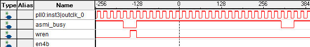
Link Copied
- Mark as New
- Bookmark
- Subscribe
- Mute
- Subscribe to RSS Feed
- Permalink
- Report Inappropriate Content
Hi AMalexander,
Check the busy signal before sending a new command. When the busy signal is deasserted, allow two clock cycles before sending a new signal. This delay allows the circuit to reset itself(IP) before executing the next command For more information click here (https://www.altera.co.jp/ja_jp/pdfs/literature/ug/ug_altasmi_parallel.pdf) Best Regards, Anand Raj Shankar (This message was posted on behalf of Intel Corporation)- Mark as New
- Bookmark
- Subscribe
- Mute
- Subscribe to RSS Feed
- Permalink
- Report Inappropriate Content
This doesn't sound right - I agree. Busy shouldn't assert unless you've issued a command to it.
Can you check the polarity of all your control signals? Confirm you're not permanently issuing a command to it - e.g. 'rden' is active HIGH (as are all the available control signals). Tie all these off low. What device family are you using? Have you tried simulating it? What parameter settings are you using when you configure the IP? Try simplifying the IP by turning optional features off. Cheers, Alex- Mark as New
- Bookmark
- Subscribe
- Mute
- Subscribe to RSS Feed
- Permalink
- Report Inappropriate Content
Hi,
Which specific operation are you executing and seeing this issue (busy high issue)? Did you reset the IP for at least 2 clock cycle before executing any operation? I think you need to provide more information on the operation sequence (such as read, erase, write etc) in your project design to access the EPCQ256. It would be better to provide screen shots of the Signal Tap on each operation steps. Regards, nyusof (This message was posted on behalf of Intel Corporation)- Mark as New
- Bookmark
- Subscribe
- Mute
- Subscribe to RSS Feed
- Permalink
- Report Inappropriate Content
nyusof,
I think the important statement in the original post is --- Quote Start --- before I even start to send anything to the epcq the busy signal is high --- Quote End --- Cheers, Alex- Mark as New
- Bookmark
- Subscribe
- Mute
- Subscribe to RSS Feed
- Permalink
- Report Inappropriate Content
Ok so I have determined that the busy signal is not high before sending the commands.
My problem now though is that I cannot seem to be able to read and write to the epcq. my current steps are to enable 4 byte addressing then write an 8 bit number to the first register of the epcq (H'00000000) then read that number back to make sure I know how to do it before I start doing more but even this is proving to be challenging. I'm including my code and a screenshot of signal tap. Can somebody tell me if I am doing this right. I feel like its pretty straightforward on the datasheet but I just can't seem to get it to work. Also this is the board I am using here: http://www.terasic.com.tw/cgi-bin/page/archive.pl?language=english&categoryno=167&no=816module battery_power_on_timer(
input wire clk_5MHz,
input wire reset_n,
// ASMI Interface inputs
input wire asmi_busy,
input wire data_in,
input wire data_valid,
input wire illegal_write,
// input wire rdid_in,
input wire read_address_in,
input wire status_in,
// Battery Powered INPUTS
input wire on_battery_power,
// Battery On Time Interface
output wire battery_on_out,
// ASMI Interface outputs
output reg addr_out,
output reg data_out,
output reg en4b_addr,
output reg ex4b_addr,
output reg rden,
output reg read,
output reg read_status,
output reg sector_protect,
output reg wren,
output reg write
);
// Registers here
reg state;
reg data_out_reg;
reg stage, stage1, stage2;
// State Machine Parameter Defination
parameter enable_4baddr = 8'b00000000;
parameter writing = 8'b00000001;
parameter reading = 8'b00000010;
parameter wait_1 = 8'b00000100;
parameter wait_2 = 8'b00001000;
parameter wait_3 = 8'b00010000;
parameter stop_it = 8'b00100000;
// Other Parameters
parameter time_record_address = 32'h00000000;
initial begin
state <= enable_4baddr;
addr_out <= time_record_address;
data_out <= 8'b00000011;
end
//main module
always @(posedge clk_5MHz, negedge reset_n)
begin
if(reset_n == 0)
begin // Reset everything
state <= 0;
end
else
begin
if(on_battery_power == 1) begin
if (state == enable_4baddr) begin
if(asmi_busy == 0) begin
if(stage == 0) begin
wren <= 1;
en4b_addr <= 1;
stage <= 1;
end
else begin
wren <= 0;
en4b_addr <= 0;
stage <= 0;
state <= wait_1; // wait two clock cycles before issuing new command
end
end
end
if (state == wait_1)begin
if(stage == 0)begin
stage <= 1;
end
else begin
state <= writing;
stage <= 0;
end
end
if(state == writing) begin
addr_out <= time_record_address;
if(asmi_busy == 0) begin
if(stage1 == 0) begin
wren <= 1;
write <= 1;
stage1 <= 1;
end
else begin
wren <= 0;
write <= 0;
stage1 <= 0;
state <= wait_2; // wait two clock cycles before issuing new command
end
end
end
if (state == wait_2)begin
if(stage == 0)begin
stage <= 1;
end
else begin
state <= reading;
stage <= 0;
end
end
if(state == reading) begin
if(asmi_busy == 0) begin
if(stage2 == 0) begin
read <= 1;
rden <= 1;
stage2 <= 1;
data_out_reg <= data_in;
end
else begin
read <= 0;
rden <= 0;
stage2 <= 0;
state <= stop_it;
end
end
end
end
else begin// else battery power off
end
end
end
endmodule
Here are the results: I first enable 4 byte addressing then write to the epcq then try to read from it. addr_out is the address I'm reading/writing to. data in is the random 8 bit number I'm writing to the epcq and data_out is where I am expecting to see the same number after I read; however, I only ever see FFh as an output on data_out instead of 03h as I would expect. I know that the read command hasn't finished in this screenshot but know that data_out does not change when the read command is done. (I was having a hard time fitting everything in the signal tap window.) the read_address shows the address that is being read from and this seems to be working fine. any help is greatly appreaciated. https://alteraforum.com/forum/attachment.php?attachmentid=14476&stc=1
- Mark as New
- Bookmark
- Subscribe
- Mute
- Subscribe to RSS Feed
- Permalink
- Report Inappropriate Content
I haven't looked through the code in detail but it strikes me as a little too simple to do what you're hoping. I suggest you look at writing your code as a 'case' statement - it lends itself to that. If/else statements can be made to work. However, the resulting code is (arguably) less readable.
I can't see anything in the code that's generating the serial access protocol to the memory. I'm not really sure what I'm looking at... I can see 'data_out_reg' being given a value but is then never used. You mention enabling 4-byte addressing. However, I can't see that in your code. Are you issuing a 'write enable' command to your EPCQ? You need to precede any write/erase command with a write enable (command 0x06). Are you simulating this? Some of the coding issues will present themselves in doing so. Cheers, Alex- Mark as New
- Bookmark
- Subscribe
- Mute
- Subscribe to RSS Feed
- Permalink
- Report Inappropriate Content
The code is for the ASMI parallel IP Core that is used to interface to the epcq. the datasheet for that is here https://www.altera.com/content/dam/altera-www/global/en_us/pdfs/literature/ug/ug_altasmi_parallel.pdf (https://www.altera.com/content/dam/altera-www/global/en_us/pdfs/literature/ug/ug_altasmi_parallel.pdf)
per the data sheet for the asmi block I believe I am doing it right but I'm not getting the expected results. Here is a better picture of signal tap that shows the signals: https://www.alteraforum.com/forum/attachment.php?attachmentid=14493 In the image you can see I am asserting "wren" (write_enable) and "en4b" to enable 4 byte addressing then I assert "wren" and "write" to write to the epcq the value in data_in[7..0] (data inserted to epcq)to the address on addr_out[31..0]. finally I assert "rden" (read_enable) and "read" to read from the addr_out[31..0] register and I'm expecting to see the same bits on data_out[7..0] as data_in[7..0] after the read operation but I see FFh instead of the expected 10h. hopefully that makes sense. I'm still new to Verilog/altera so bare with me as I stumble my way through this.
- Mark as New
- Bookmark
- Subscribe
- Mute
- Subscribe to RSS Feed
- Permalink
- Report Inappropriate Content
Sorry - indeed that makes much more sense...
Re-read the description of the 'wren' port: --- Quote Start --- Active-high port that allows write and erase operations to be performed as long as it stays asserted. --- Quote End --- Keep it asserted for the duration of the operations it's required for. You're only asserting it for a single clock cycle. Cheers, Alex- Mark as New
- Bookmark
- Subscribe
- Mute
- Subscribe to RSS Feed
- Permalink
- Report Inappropriate Content
hello, just wanted to say thank you for the help and that I have it figured out now. As it turns out, I did need to hold the wren active-high while the write mode took place. Also on my dev board there are mode select (MSEL) pins which I had in active serial x4 mode but when I changed it to FPPx8 mode it worked.
thanks again for the help, Alex- Subscribe to RSS Feed
- Mark Topic as New
- Mark Topic as Read
- Float this Topic for Current User
- Bookmark
- Subscribe
- Printer Friendly Page