- Mark as New
- Bookmark
- Subscribe
- Mute
- Subscribe to RSS Feed
- Permalink
- Report Inappropriate Content
The moving average filter consists of 3 components:
Counter - to increment the ram address Ram - to store 4 data samples average logic - computes the average and the result is latched These three components I have tested using a testbench for each component an the results were as expected. However when I included a top level design file that instantiates these three components, the internal signal takes the value of unknown when it should be summing that data at the input. (The signal initially is cleared by means of an asynchronous reset pulse)p_average_logic : process(i_clk, i_rst)
begin
if(i_rst = '0') then
o_dout <= (others => '0');
dout <= (others => '0');
elsif(rising_edge(i_clk)) then
if(i_en = '1' and i_ce = '1') then
dout <= dout + ("00" & i_din);
elsif(i_en = '1' and i_updt = '1') then
			o_dout <= dout(13 downto 2);
else dout <= (others => '0');
end if;
end if;
end process p_average_logic;
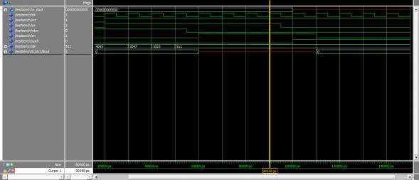
Attached is the result of the simulation of the top level design. Between 60 and 90 ns of simulation time the signal goes unkown, in that step it should be executing the following code. (taken from the code shown above) elsif(i_en = '1' and i_updt = '1') then
o_dout <= dout(13 downto 2); This occurs with a warning from the simulator : # ** Warning: There is an 'U'|'X'|'W'|'Z'|'-' in an arithmetic operand, the result will be 'X'(es).# Time: 60 ns Iteration: 1 Instance: /testbench/U2/U3 What could give rise to such an event? Especially since the component has already been tested individually?
Link Copied
5 Replies
- Mark as New
- Bookmark
- Subscribe
- Mute
- Subscribe to RSS Feed
- Permalink
- Report Inappropriate Content
I would assume that i_din is unknown, as this will cause dout to become unknown.
Without the full code and the testbench, thats the only answer with the code given.- Mark as New
- Bookmark
- Subscribe
- Mute
- Subscribe to RSS Feed
- Permalink
- Report Inappropriate Content
Thank you for you reply Tricky!
I have attached the project folder, all design files are found in vhd_files. stimulus.vhd contains the input stimuli and testbench.vhd is the top level design file. I have created a .do file, if you change the path to the project directory and execute it with modelsim will bring up the simulated result. Thanks a lot for your help!- Mark as New
- Bookmark
- Subscribe
- Mute
- Subscribe to RSS Feed
- Permalink
- Report Inappropriate Content
as I suspected, i_din is 'U'. This is the output of the ram. You need to ensure the ram contains values before reading them.
- Mark as New
- Bookmark
- Subscribe
- Mute
- Subscribe to RSS Feed
- Permalink
- Report Inappropriate Content
That solved the issue but i do not quite understand why.
at exactly 60 ns, the output of the ram goes from undefined to some value stored in it, and at that time the average_logic module is enabled, thus shouldn't it(average_logic module) consider the new value that just changed from 'U' ? since the simulation assumes ideal conditions?- Mark as New
- Bookmark
- Subscribe
- Mute
- Subscribe to RSS Feed
- Permalink
- Report Inappropriate Content
The simulation only takes the values given to it. The ram obviously has no values set for the addresses input up until that time.
Reply
Topic Options
- Subscribe to RSS Feed
- Mark Topic as New
- Mark Topic as Read
- Float this Topic for Current User
- Bookmark
- Subscribe
- Printer Friendly Page