- Mark as New
- Bookmark
- Subscribe
- Mute
- Subscribe to RSS Feed
- Permalink
- Report Inappropriate Content
Hello,
I have a Max1000 development board and would like to perform a remote system upgrade with it.
I have programmed an SPI interface to send the required data. (Here not necessarily SPI must be used, but I think another interface does not change my problem). Now I want to program the RSU without the Nios.
I have gotten to the point where I need the dual boot ip core to configure the "dual compressed image". An onchip-Ram to store the necessary data and an onchip-Flash to write to the CFM. But here my flash has only an address size of 17 bits, but to rewrite the CFM the address must be at least 18 bits.
Am I missing something here? Is it possible to rewrite the CFM with SPI like this?

Link Copied
- Mark as New
- Bookmark
- Subscribe
- Mute
- Subscribe to RSS Feed
- Permalink
- Report Inappropriate Content
What are your settings under "Configuration Mode" (that section is minimized in your screenshot)?
Also, which exact MAX 10 device is on that board (10Mxx)? The size of the CFM is different for different members of the family.
- Mark as New
- Bookmark
- Subscribe
- Mute
- Subscribe to RSS Feed
- Permalink
- Report Inappropriate Content
Under the settings stand:
Configuration Scheme: Internal Configuration
Configuration Mode: Dual Compressed Images
This is how I have seen it in various videos on the subject. And I have an 10M08SAU169C8G on the board.
- Mark as New
- Bookmark
- Subscribe
- Mute
- Subscribe to RSS Feed
- Permalink
- Report Inappropriate Content
That's weird. Are you using Platform Designer? I'm guessing yes. Are you just exporting the Avalon interface out of the system and then connecting your control mechanism to it externally? What are you using for control if not Nios?
- Mark as New
- Bookmark
- Subscribe
- Mute
- Subscribe to RSS Feed
- Permalink
- Report Inappropriate Content
Yes, I am using the Platform Designer. I put the onchip-flash, onchip-memory and dual_boot in a Qsys file and added it to the project. I link the signals externally. I'll add a scrrenshot of it.

I would like to implement the RSU not with the Nios, but with an own logic circuit. So that I write the VHDL code myself to read and write the register and read from the flash or write on the flash. I could already read the register and got the expected data. It should not really change my problem if the Nios or something else is connected, because it does not increase the size of the addresbus from the onchip flash.
This is how a part of my interface to the onchip flash should look like then. I read the register, then I write in the register the command to clear a page and wait until the bit in the register is set that the clear was successful. But no matter how that looks, it shouldn't change my problem.
   -- -------------------------------------------------------------------------------------
    --  erase Page or sector
    -- -------------------------------------------------------------------------------------
	 procedure register_erase (
    i_data_register       : in  std_logic_vector(31 downto 0)) is
    begin
	     CASE operation_register IS

	     -- 1. read in which mode flash is
        -- 2. write erase command in register 0x01
	     -- 3. Check register 0x00 wheather erase was sucessful
		  -- 4. reset register 0x01
		  WHEN mode_start =>
		      onchip_flash_register_addr <= '0';
		      onchip_flash_register_read <= '1';
				IF count_flash <= 5 THEN
				    count_flash <= count_flash + 1;
				ELSE
				    IF onchip_flash_register_readdata (1 DOWNTO 0) = "00" THEN
				        -- Flash is in IDLE mode
						  operation_register <= mode_write;
						  count_flash <= 0;
				    ELSE
					     -- Flash is busy
						  count_flash <= 0;
						  count_error_flash <= count_error_flash + 1;
					 END IF;
				END IF;

		  WHEN mode_write =>
		      onchip_flash_register_read <= '0';
				onchip_flash_register_addr <= '1';
		      onchip_flash_register_write <= '1';
				onchip_flash_register_writedata <= i_data_register;
				-- wait a few ns to write in register
				IF count_flash <= 10 THEN
				    count_flash <= count_flash + 1;
				ELSE
				    count_flash <= 0;
				    operation_register <= mode_check;
				END IF;

		  WHEN mode_check =>
		      onchip_flash_register_read <= '1';
				onchip_flash_register_addr <= '0';
		      onchip_flash_register_write <= '0';
				-- wait a few ns to read from register
				IF count_flash <= 10 THEN
				    count_flash <= count_flash + 1;
				ELSE
				    IF onchip_flash_register_readdata (4 DOWNTO 4) = "1" THEN
				        -- erase was sucessful
						  count_flash <= 0;
						  count_error_flash <= 0;
				        operation_register <= mode_reset;
					 ELSE
					     -- erase wasnt sucessful
						  count_flash <= 0;
						  count_error_flash <= count_error_flash + 1;
						  operation_register <= mode_write;
					 END IF;
				END IF;

		  WHEN mode_reset =>
		      onchip_flash_register_read <= '0';
				onchip_flash_register_addr <= '1';
		      onchip_flash_register_write <= '1';
				onchip_flash_register_writedata <= x"FF800000";
				-- wait a few ns to write in register
				IF count_flash <= 5 THEN
				    count_flash <= count_flash + 1;
				ELSE
				    count_flash <= 0;
				    operation_register <= mode_start;
					 operation_flash <= mode_wait;
					 onchip_flash_register_addr <= '0';
		          onchip_flash_register_write <= '0';
				END IF;

		  WHEN OTHERS =>
		      operation_register <= mode_start;

		  END CASE;

    end register_erase;
- Mark as New
- Bookmark
- Subscribe
- Mute
- Subscribe to RSS Feed
- Permalink
- Report Inappropriate Content
- Mark as New
- Bookmark
- Subscribe
- Mute
- Subscribe to RSS Feed
- Permalink
- Report Inappropriate Content
Thanks for the example project. I found an answer to my question, however I don't quite understand why? You write in line 854 that the maximum address is 13ffh (79871). In the Platform Designer it says under Flash Memory that the largest address is 0x4dfff (319487 or 8*79871 - 1). Why do you divide the addresses by 8?
Furthermore I don't understand your page_erase_addr in line 740. Of course you take 19 bits, because there is so much space in the register. But why do you start counting up in the middle?
- Mark as New
- Bookmark
- Subscribe
- Mute
- Subscribe to RSS Feed
- Permalink
- Report Inappropriate Content
1. As in the UFM user guide at (https://www.intel.com/content/www/us/en/docs/programmable/683180/18-0/sector-address.html), you have to convert the sector addresses to the avalon mm addresses. This process done by dividing 4 not 8 (2 bit shifting).
2. Page erase operation at below the line ~740 is just UFM erase. Actually you can add here CFM sectors as well but I done CFM sectors erasing in sector erase mode. As you can see in UFM user guide (https://www.intel.com/content/www/us/en/docs/programmable/683180/18-0/ufm-and-cfm-array-size.html) 10M08 devices has 8+8= 16 pages in UFM sections. If you look at the flash ip, you can see that UFM sectors are between 0 and 0x07fff. It is normal sector addressing. It means approximately 0 - 0x2000 in avalon addressing and that is equal to 0-8192 bits. So we have 16 pages total, then one page's address is 8192/16=512 in avalon addressing. For this reason I increase the UFM page erase addresses by 512 for each page of UFM. I hope it doesn't confusing. In fact it is hard to understand that addressing and documentations about it is very poor.
- Mark as New
- Bookmark
- Subscribe
- Mute
- Subscribe to RSS Feed
- Permalink
- Report Inappropriate Content
Now I finally understand how the addressing works. Thank you for your quick and very helpful answers.
- Mark as New
- Bookmark
- Subscribe
- Mute
- Subscribe to RSS Feed
- Permalink
- Report Inappropriate Content
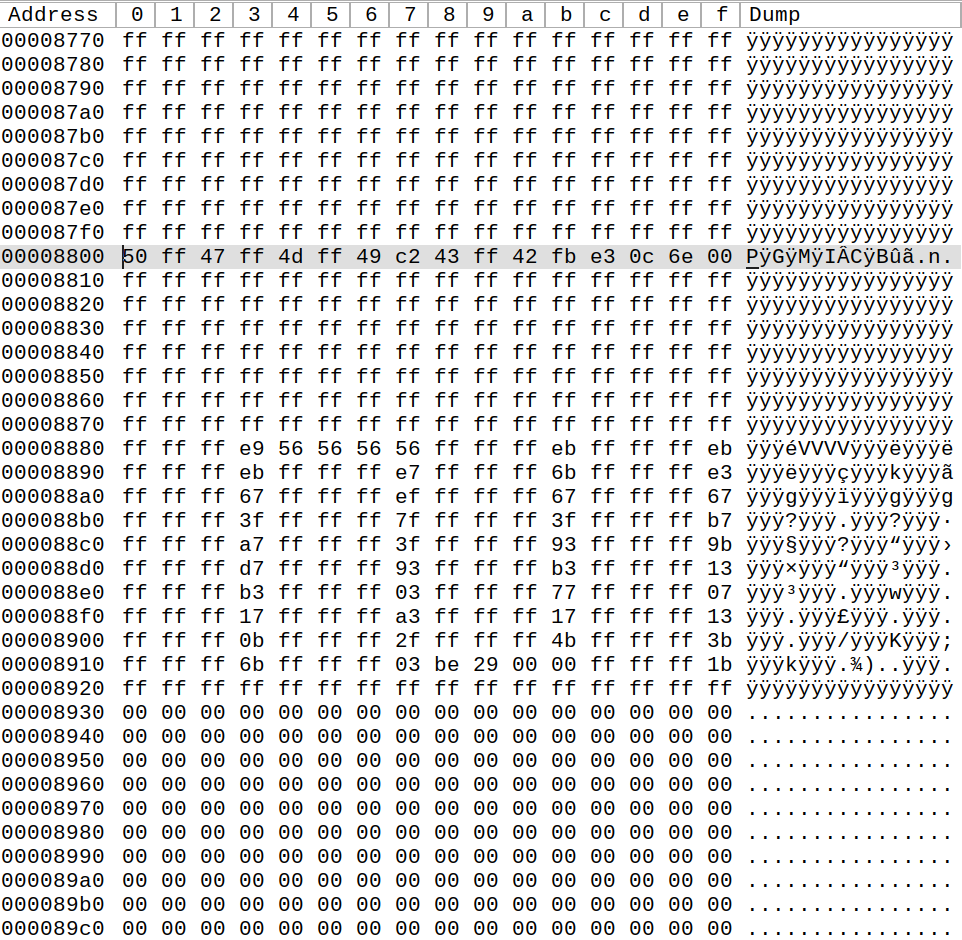
@jozephka99 Why is it ok to start programming the flash data from either address 0xAC00 or 0x2000, based on the addresses shown in the Flash IP configuration, while the addresses shown in the .map file are a bit higher? In the map it shows 0x8800 as start of CFM1, so 0x2200, and 2B800 as start of CFM0, so 0xAE00.
This is based on your lines 373 - 378 from the file manual_rsu.vhd. I'm guessing your code works, so it is correct to use the addresses of the Flash IP block and not to use the .map information.
- Mark as New
- Bookmark
- Subscribe
- Mute
- Subscribe to RSS Feed
- Permalink
- Report Inappropriate Content
It is because the actual data -that differs from 1's- in that .rpd file begins from 0x8800 (0x2200) (CFM1) and 0x2B800 (0xAE00) (CFM0). Data before this addresses is full of "FF"s that is default value of OC RAM. (You can see that if you open the .rpd file with a HEX editor.) .map tells us that you don't have to change these addresses because you already erase the OC RAM before writing it and they are already in the default values. So you can either begin from addresses that shown in IP core like me, or you can use .map addressings. But I think .map addressings can change and it is not that easy to do it in dynamic way.
- Mark as New
- Bookmark
- Subscribe
- Mute
- Subscribe to RSS Feed
- Permalink
- Report Inappropriate Content
Hmm, when I open the <project>_cfm1_auto.rpd, the first rule contains some data already, followed by some FF bytes, but not 0x200 worth.
I do see a lot of FF bytes starting a bit before halfway the file, so that's probably what you mean... Does this mean that I need to send the file back to front to the FPGA?
The file is attached as "proof", just inside a .zip because direct .rpd upload is not allowed here.
I'm generating the .rpd files through "convert programming file" and then ticking "create config data RPD".
Additional question: in "Options/Boot info..." I switch the "RPD File Endianness" to "Big endian" to save myself the bit-swap on the FPGA, right?
- Mark as New
- Bookmark
- Subscribe
- Mute
- Subscribe to RSS Feed
- Permalink
- Report Inappropriate Content
The file that you send is just CFM1 file. It is cutted from <project>_auto.rpd file. If you look at that file you can see CFM1 section starts from 0x8800. The FF's from halfway is the empty spaces in the logic I think.
But here a new question appears. The CFMx_auto.rpd files cutted from 0x8800 and 0x2B800 but when write them to OC RAM, I write them from 0x8000 and 0x2B000. So in my understanding the exact addressing is not that important unless the .rpd's meaningful bits fits in OC RAM.
I swap the bits manually but it is more logical to do it from programming file converter of course.
- Mark as New
- Bookmark
- Subscribe
- Mute
- Subscribe to RSS Feed
- Permalink
- Report Inappropriate Content
I'm still having issues with programming the Flash...
As far as I understand https://www.intel.com/content/www/us/en/docs/programmable/683180/18-0/ufm-program-write-operation.html , I was able to convert this to a state machine in VHDL, programming_logic.vhd .
When I simulate this design with the correct platform (just dual boot IP and Flash IP), the simulation shows lot's of programming operations. So this lead me to believe this state machine is correct and I can indeed program a CFM sector of the Flash memory.
However, when I transfer my design to my MAX1000 FPGA (Intel MAX10M08), it goes to the Error state once the first byte has been programmed.
According to the guide, there are only 3 possible causes for this:
- "burst count is not equal to 1". I clearly set this to 1 in my code, so this cannot be the issue;
- "The given address is out of range". No matter what address I give (0x2000 or 0x2200), the error is not resolved. So this also does not seem to be the issue.
- "The write protection mode is not clear". I clearly disable this, so this cannot be the issue;
Any ideas to why the On-chip Flash IP core might indicate an error? Feel free to browse through the attached code.
(no idea to why this error can be caused is 'stupid'. FPGA and VHDL are not my strong suite, so feel free to spit out any cause for the error.)
- Mark as New
- Bookmark
- Subscribe
- Mute
- Subscribe to RSS Feed
- Permalink
- Report Inappropriate Content
Can you try sector erase operation before writing data to the flash.
- Mark as New
- Bookmark
- Subscribe
- Mute
- Subscribe to RSS Feed
- Permalink
- Report Inappropriate Content
@jozephka99 Valid remark. I did not specify it, but I do a sector erase operation before I try to write to the flash. This logic is contained in a separate entity and indeed not in the uploaded programming_logic.
- Mark as New
- Bookmark
- Subscribe
- Mute
- Subscribe to RSS Feed
- Permalink
- Report Inappropriate Content
				WHEN AN_WR_SUCC =>
					-- make sure IP is indeed idle again --
					IF csr_readdata(1 DOWNTO 0) = "00" THEN
						-- write success is bit on pos. 3 --
						IF csr_readdata(3) = '1' THEN
							state <= UPD_VAR;
						ELSE
							state <= ERROR;
						END IF;
					ELSE
						state <= AN_WR_SUCC;
					END IF;
In here, it goes to error state -if write success bit not set- at the first cycle after IP is idle. Maybe the success bit doesn't set at the first cycle. Can you wait until this bit set? You migth successfuly write the data to flash. You should try also read the address that you wrote and check your data if the write had succeed.
- Mark as New
- Bookmark
- Subscribe
- Mute
- Subscribe to RSS Feed
- Permalink
- Report Inappropriate Content
Changed the logic to just wait until that bit is set. That made no difference.
I can program 4 bytes, to whatever address within the erased CFM and once I try to do the next 4 bytes, it never sets that success bit.
Just to clarify, I can write data, e.g. 0x"ffe2ff0a", to any address. I tried with 0x2000, 0x2001, 0x2002, 0x2008 and 0x2200. That first write always sets the success bit. If I then do address <= address + 1 and initiate a second write with data, it never sets the success bit. I also tried this with 0x"ffffffff" as data, to see it that would work, but that results in the same.
The manual does state:
6. You have to enable back the write protection mode when the program operation completes. Write 1 into the write protection register for the corresponding sector through the Avalon-MM control interface.
Note: Check the status register after each write to make sure the program operation is successful (write successful).
I interpreted this as "once you have performed all your write operations, put write protection back on". But maybe the manual means "after each 4 byte write, put back on the write protection"? So could it be that because I fail to put back the write protection after my first write operation, the on-chip flash IP core goes into error?
But why doesn't the simulation show this, if that's the case? Simulation shows I can program the on-chip flash just right, going through the addresses... (this is what really baffles me. That the simulation says: VHDL is ok and does program the flash; while the actual FPGA says: no, not correct)
Will now work on that read-back logic to see if my data did make it into flash or not. But if that's the case, I cannot trust the signals in the status register of the on-chip flash IP core, which would be annoying ...
- Mark as New
- Bookmark
- Subscribe
- Mute
- Subscribe to RSS Feed
- Permalink
- Report Inappropriate Content
"I interpreted this as 'once you have performed all your write operations, put write protection back on'. ", Yes you're right. It works like this.
Can you succeed with my code above? Sometimes rewriting the code is much easier then fixing it.
Also I think simulations are not very reliable.
- Mark as New
- Bookmark
- Subscribe
- Mute
- Subscribe to RSS Feed
- Permalink
- Report Inappropriate Content
Update:
The read-back showed that data had indeed not made it into the Flash memory, and hence the success bit was correctly unset.
Just to be sure, I recreated my entire project from scratch again. That version is attached to my post here. This showed the same behaviour.
Through trial-and-error, I d think I discovered what the error is: my FPGA (MAX1000) seems to be unable to deal with type conversions...
Let me explain. To increment my data address after each program operation, I defined it as a natural that I convert to an STD_LOGIC_VECTOR when I want to want to put the address on the data_address interface of the On-chip Flash IP core.
In pseudo-code this means I do:
signal current_address : natural := CFM_BASE address; -- 0x2000 if CFM1
While not entire CFM programmed{
    data_address <= std_logic_vector(to_unsigned(curr_addr,data_address'LENGTH)) ;
    <program operation and analyse result>
    curr_address <= curr_address + 1;
}
While this should work, as this is normal VHDL 93 code, the FPGA can't deal with this. As soon as the increment happens, the following programming operation results in ERROR. I have tried this with integer type too and even with unsigned(16 downto 0). All with the same result. As soon as that increment is hit, the next write operation results in an error.
However, if I define the current address as an STD_LOGIC_VECTOR already and update it using an xor operation as a try-out, I can program the 2 created addresses as much as desired.
In pseudo-code, this becomes:
signal curr_addr : STD_LOGIC_VECTOR(16 DOWNTO 0) := CFM_BaseAddress;
While not entire CFM programmed{
    data_address <= curr_addr;
    <program operation and analyse result>
    curr_addr <= curr_addr xor "00000000000000001"; -- just as try-out
}
I don't understand how this can happen. Do I need to enable extra settings to enable my FPGA to deal with natural signals and their conversion to STD_LOGIC_VECTOR? Settings that are not necessary for the simulation, as simulation can deal with natural and the conversion.
As it stands now, I would have to include a 17 bit adder into my design, just to be able to increment my STD_LOGIC_VECTOR address holder... which is, quite frankly, stupid.
Anyone ever come across this too and remember what his/her solution was?
@jozephka99 : since your code also uses this increment strategy, I suspect executing your code will result in the same error. I still have to study how to use your code and program it to my MAX1000, that's for the coming days.
- Mark as New
- Bookmark
- Subscribe
- Mute
- Subscribe to RSS Feed
- Permalink
- Report Inappropriate Content
For those who come across this later: I solved my problem.
I again restarted from scratch and the biggest changes I made:
- not use natural, only UNSIGNED for variables to count with;
- transform my 2 process state machine into a single process state machine;
- full process sensitivity list.
No idea what actually solved the issue, and what the issue was, but now I can send the RPD file through UART and program it in flash. Indeed using address 0x2000 for CFM1, so the IP core address (divided by 4 of course).
@jozephka99 : thanks for your help while I was figuring this out!
- Subscribe to RSS Feed
- Mark Topic as New
- Mark Topic as Read
- Float this Topic for Current User
- Bookmark
- Subscribe
- Printer Friendly Page