Hello,
I am trying to use testbenches in a big project. Quartus created tb itself and I just added a few lines within this testmodule: initial begin clk_clk = 0; end always# 10 clk_clk = ~clk_clk Then by using RTL simulation I opened modelsim which added all wires of the project correctly but it is not simple generate clock pic related 1) I did not find any explanation about grey lines. Why it even Pu0 (pull down?) 2) What did i wrong? I tried to follow altera RTL simulation guide Looking forward any help :c i am very new to Quartus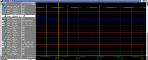
链接已复制
11 回复数
Hi,
--- Quote Start --- initial begin clk_clk = 0; end always# 10 clk_clk = ~clk_clk --- Quote End --- Let me know, 1. Are you able to compile Design & Testbench successfully? 2. All Inputs/Outputs are declared & initialized properly or not(declaration of clk_clk should be reg)? 3. can you provide code? Let me know if this has helped resolve the issue you are facing or if you need any further assistance. Best Regards Vikas Jathar (This message was posted on behalf of Intel Corporation)Thank you for all replies!
Well. Firtsly I created Testbench skeleton by Processing -> Start -> Test bench Writer Then i added its link in Assingments -> Settings -> Simulation -> Native link settings I modified TB with a few lines for modelsim to generate clock signal (just to try how it works) But it is not work, even if i try to assing anything to 1'b1 or whatever. Please guide how it supposed to work :c clk_clk generated as regHi,
Replace sysclk by sysclk_period It`s simple just provide input stimulus for example as follows & simulate,always @(posedge SYSCLK_PERIOD) begin
# 5 reset_reset_n = 1;
# 50 reset_reset_n = 0;
# 100 reset_reset_n = 1;
# 25 reset_reset_n = 0;
# 55 reset_reset_n = 1;
end find the attachment for screenshot. Let me know if this has helped resolve the issue you are facing or if you need any further assistance. Best Regards Vikas Jathar (This message was posted on behalf of Intel Corporation)
I replaced but still getting those strange pictures. I am sorry, but clock_period is a parameter (constant) how you made it posedge? Could you please provide me with your testbench file?
Thank you for your attention!Nothing helps me :c
Maybe smth broken in Native link connetion. But when I intentionally made mistake in .vt file, Modelsim reported me about it so it sees and updates it during RTL simulation. You seemed to simulate this project without Quartus, how?Hi,
I created own simple design file relative to the .vt file, refer the attached files & try yourself with fresh new project in Quartus tool. Let me know if this has helped resolve the issue you are facing or if you need any further assistance. Best Regards Vikas Jathar (This message was posted on behalf of Intel Corporation)RTL simulation finally works! I used your guide and this helps!
Now i see it all the matter of names. I've used the name of TB file in native link settings, not the name, which Quartus gave to TB module. Thank you a lot!